Return to Section TOC
Return to Section TOC
Return to Master TOC
Return to Master TOC
TROUBLESHOOTING AND REPAIR | ||
|
|
BOOST POWER SUPPLY BOARD
REMOVAL AND REPLACEMENT PROCEDURE (Continued)
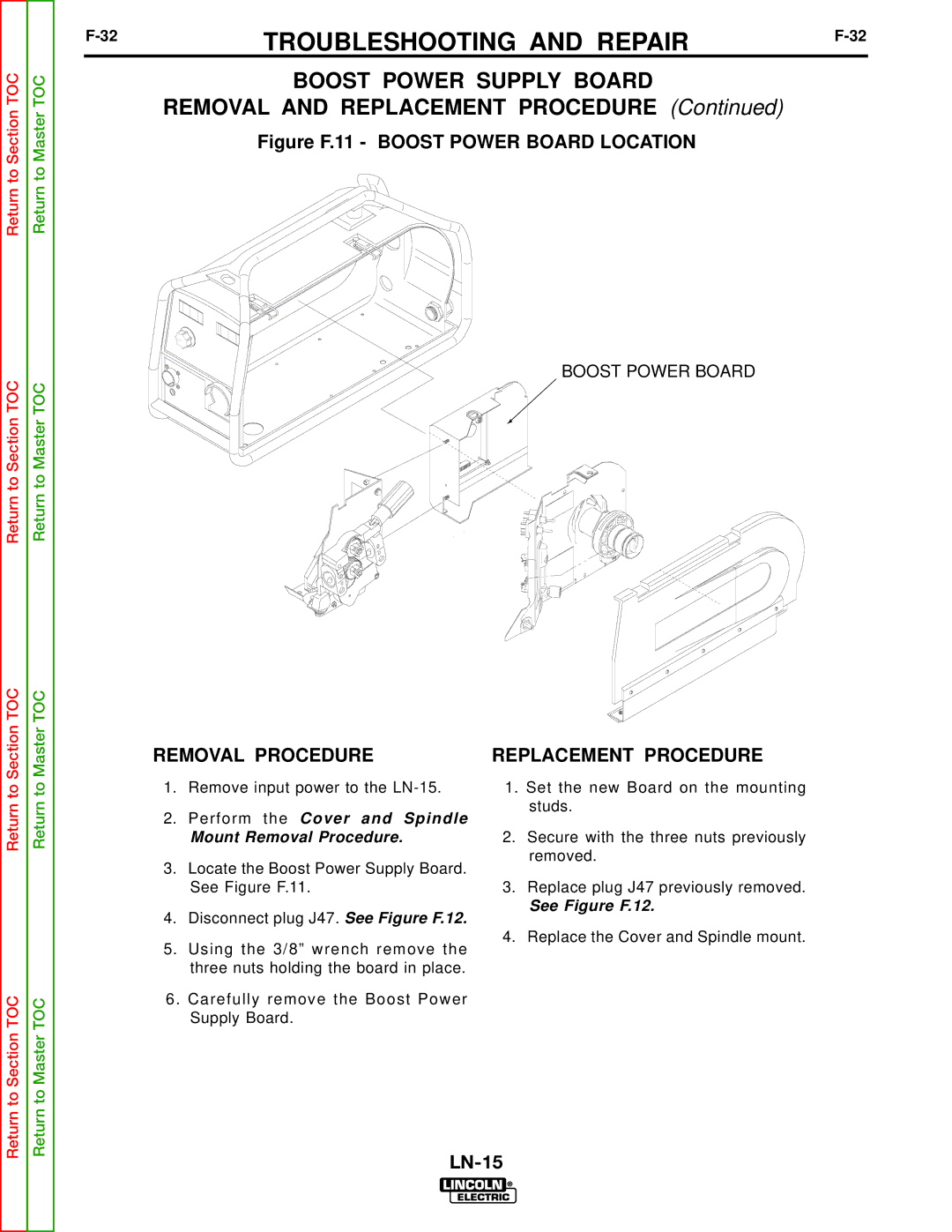
Figure F.11 - BOOST POWER BOARD LOCATION
BOOST POWER BOARD
Return to Section TOC
Return to Section TOC
Return to Master TOC
Return to Master TOC
REMOVAL PROCEDURE
1.Remove input power to the
2.Perform the Cover and Spindle
Mount Removal Procedure.
3.Locate the Boost Power Supply Board. See Figure F.11.
4.Disconnect plug J47. See Figure F.12.
5.Using the 3/8” wrench remove the three nuts holding the board in place.
6. Carefully remove the Boost Power Supply Board.
REPLACEMENT PROCEDURE
1.Set the new Board on the mounting studs.
2.Secure with the three nuts previously removed.
3.Replace plug J47 previously removed.
See Figure F.12.
4.Replace the Cover and Spindle mount.
