TROUBLESHOOTING AND REPAIR | ||
|
|
CONTACTOR REMOVAL AND REPLACEMENT PROCEDURE (Continued)
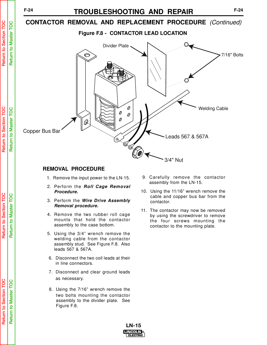
Figure F.8 - CONTACTOR LEAD LOCATION
Divider Plate
Copper Bus Bar
REMOVAL PROCEDURE
1.Remove the input power to the
2.Perform the Roll Cage Removal
Procedure.
3.Perform the Wire Drive Assembly
Removal procedure.
4.Remove the two rubber roll cage mounts that hold the contactor assembly to the case bottom.
5.Using the 3/4” wrench remove the welding cable from the contactor assembly stud. See Figure F.8. Also leads 567 & 567A.
6.Disconnect the two coil leads at their in line connectors.
7.Disconnect and clear ground leads as necessary.
8.Using the 7/16” wrench remove the two bolts mounting the contactor assembly to the divider plate. See Figure F.8.
![]() 7/16" Bolts
7/16" Bolts
Welding Cable
 Leads 567 & 567A
3/4" Nut
9.Carefully remove the contactor assembly from the
10.Using the 11/16” wrench remove the cable and copper bus bar from the contactor.
11.The contactor may now be removed by using the screwdriver to remove the four screws mounting the contactor to the mounting plate.