TOC
TOC
THEORY OF OPERATION | ||
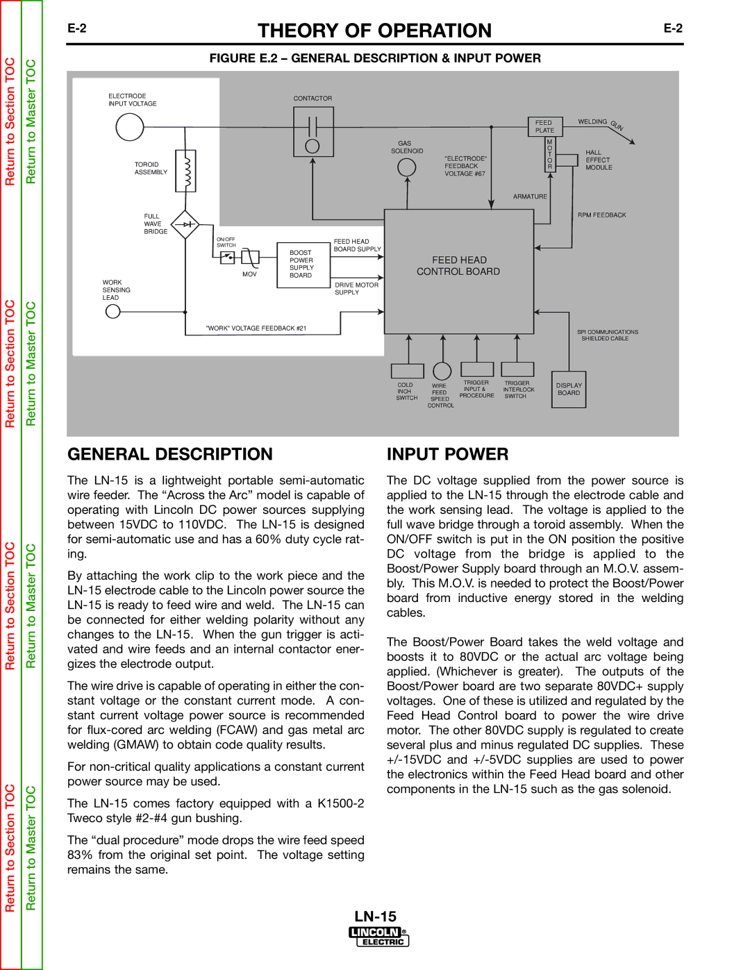
| FIGURE E.2 – GENERAL DESCRIPTION & INPUT POWER |
|
ELECTRODE INPUT VOLTAGE
TOROID
ASSEMBLY
FULL
WAVE
BRIDGE
CONTACTOR
| FEED | WELDING | |
| PLATE |
| |
GAS | M |
| |
SOLENOID | O | HALL | |
T | |||
"ELECTRODE" | EFFECT | ||
O | |||
FEEDBACK | R | MODULE | |
VOLTAGE #67 |
|
|
ARMATURE
RPM FEEDBACK
ON/OFF
SWITCH
MOV
WORK SENSING LEAD
BOOST POWER SUPPLY BOARD
FEED HEAD BOARD SUPPLY
DRIVE MOTOR SUPPLY
FEED HEAD
CONTROL BOARD
Return to Master TOC
"WORK" VOLTAGE FEEDBACK #21
SPI COMMUNICATIONS
SHIELDED CABLE
COLD | WIRE | TRIGGER | TRIGGER | DISPLAY | |
INPUT & | INTERLOCK | ||||
INCH | FEED | BOARD | |||
PROCEDURE | SWITCH | ||||
SWITCH | SPEED |
| |||
|
|
| |||
| CONTROL |
|
|
|
Return to Section TOC
Return to Section TOC
Return to Section TOC
Return to Master TOC
Return to Master TOC
GENERAL DESCRIPTION
The
By attaching the work clip to the work piece and the
The wire drive is capable of operating in either the con- stant voltage or the constant current mode. A con- stant current voltage power source is recommended for
For
The
The “dual procedure” mode drops the wire feed speed 83% from the original set point. The voltage setting remains the same.
INPUT POWER
The DC voltage supplied from the power source is applied to the
The Boost/Power Board takes the weld voltage and boosts it to 80VDC or the actual arc voltage being applied. (Whichever is greater). The outputs of the Boost/Power board are two separate 80VDC+ supply voltages. One of these is utilized and regulated by the Feed Head Control board to power the wire drive motor. The other 80VDC supply is regulated to create several plus and minus regulated DC supplies. These