Return to Section TOC
Return to Section TOC
Return to Master TOC
Return to Master TOC
THEORY OF OPERATION | ||
|
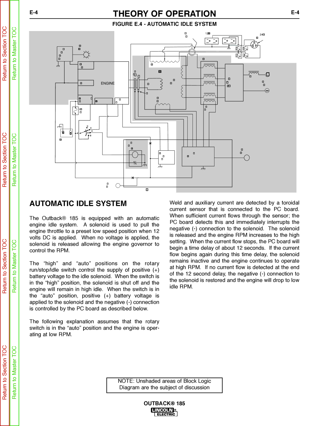
FIGURE E.4 - AUTOMATIC IDLE SYSTEM
|
|
|
|
|
|
| CURRENT | 120 VAC RECEPTACLES |
| 240 VAC |
|
|
|
|
|
|
| SENSOR |
|
| |
|
|
|
|
|
|
|
| RECEPTACLE | ||
|
|
|
|
|
|
|
|
| ||
|
| OIL LEVEL |
|
|
|
|
| CB1 | CB3 |
|
OIL |
| INDICATOR |
|
|
|
|
|
| ||
|
|
|
|
|
|
|
|
| ||
LEVEL |
|
|
|
|
|
|
| CB2 | CB4 |
|
MODULE |
|
|
|
|
|
|
| |||
(KOHLER) |
|
|
|
|
| REACTOR |
|
| ||
|
| OIL LEVEL |
|
| AUXIIARY WINDINGS |
|
|
|
| |
|
| SWITCH |
| RINGS |
| STATOR |
|
|
|
|
|
|
|
| SLIP |
|
|
|
|
| + |
|
|
|
| _ + |
| WELD |
| OUTPUT | CHOKE | |
|
|
|
|
|
|
|
| OUTPUT | ||
|
| IGNITION | ENGINE |
| ROTOR | WINDINGS |
| RECTIFIER |
| |
|
|
|
|
| STUDS | |||||
|
|
|
|
|
|
|
| (2 PHASE) |
| |
|
|
|
|
| BRUSHES |
|
|
|
|
|
|
| STARTER / | ALTERNATOR | IDLE | EXCITER |
|
|
|
| |
|
| SOLENOID | SOLENOID | WINDING |
|
|
|
| ||
|
|
|
|
|
|
|
|
|
| |
|
| 10 AMP |
|
|
|
|
| BOOST |
|
|
|
|
|
|
|
|
| WINDING |
|
| |
|
| FUSE |
|
|
|
|
|
|
|
|
|
| OFFAUTO |
|
|
|
|
|
|
|
|
_ | + | HIGH |
|
|
|
|
|
|
| |
START |
|
|
|
|
|
|
|
| ||
|
|
|
|
|
|
|
|
|
| |
BATTERY |
|
| ENGINE |
|
|
|
|
|
| |
|
|
|
|
|
|
|
|
|
| |
|
|
|
| SHUTDOWN |
|
|
|
|
|
|
|
|
|
| RELAY |
|
|
| OUTPUT |
| |
|
|
|
|
|
| AUTOMATIC | OUTPUT | CONTROL |
| |
|
|
|
|
|
| IDLER | CONTROL CIRCUIT |
|
| |
|
|
|
|
|
| CIRCUIT |
|
|
|
|
|
|
| HOUR |
|
|
|
|
|
|
|
|
|
| METER |
| FIELD / CONTROL PC BOARD |
|
|
| ||
|
|
|
|
|
|
|
| |||
Return to Section TOC
Return to Master TOC
AUTOMATIC IDLE SYSTEM
The Outback® 185 is equipped with an automatic engine idle system. A solenoid is used to pull the engine throttle to a preset low speed position when 12 volts DC is applied. When no voltage is applied, the solenoid is released allowing the engine governor to control the RPM.
The “high” and “auto” positions on the rotary run/stop/idle switch control the supply of positive (+) battery voltage to the idle solenoid. When the switch is in the “high” position, the solenoid is shut off and the engine will remain in high idle. When the switch is in the “auto” position, positive (+) battery voltage is applied to the solenoid and the negative
The following explanation assumes that the rotary switch is in the “auto” position and the engine is oper- ating at low RPM.
Weld and auxiliary current are detected by a toroidal current sensor that is connected to the PC board. When sufficient current flows through the sensor; the PC board detects this and immediately interrupts the negative
Return to Section TOC
Return to Master TOC
NOTE: Unshaded areas of Block Logic Diagram are the subject of discussion