Return to Section TOC
Return to Section TOC
Return to Master TOC
Return to Master TOC
THEORY OF OPERATION | ||
|
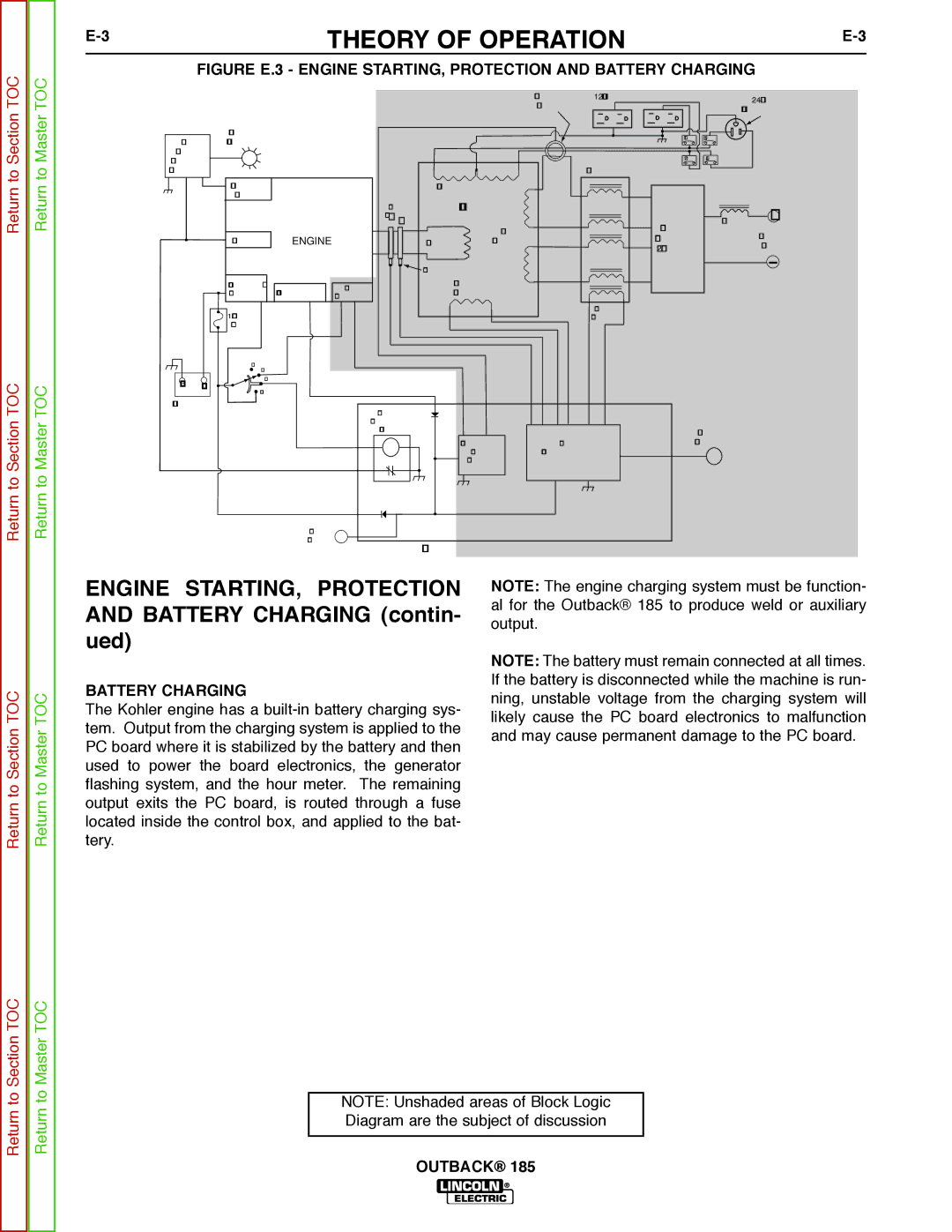
FIGURE E.3 - ENGINE STARTING, PROTECTION AND BATTERY CHARGING
|
|
|
|
|
|
| CURRENT | 120 VAC RECEPTACLES |
| 240 VAC |
|
|
|
|
|
|
| SENSOR |
|
| |
|
|
|
|
|
|
|
| RECEPTACLE | ||
|
|
|
|
|
|
|
|
| ||
|
| OIL LEVEL |
|
|
|
|
| CB1 | CB3 |
|
OIL |
| INDICATOR |
|
|
|
|
|
| ||
|
|
|
|
|
|
|
|
| ||
LEVEL |
|
|
|
|
|
|
| CB2 | CB4 |
|
MODULE |
|
|
|
|
|
|
| |||
(KOHLER) |
|
|
|
|
| REACTOR |
|
| ||
|
| OIL LEVEL |
|
| AUXIIARY WINDINGS |
|
|
|
| |
|
| SWITCH |
| RINGS |
| STATOR |
|
|
|
|
|
|
|
| SLIP |
|
|
|
|
| + |
|
|
|
| _ + |
| WELD |
| OUTPUT | CHOKE | |
|
|
|
|
|
|
|
| OUTPUT | ||
|
| IGNITION | ENGINE |
| ROTOR | WINDINGS |
| RECTIFIER |
| |
|
|
|
|
| STUDS | |||||
|
|
|
|
|
|
|
| (2 PHASE) |
| |
|
|
|
|
| BRUSHES |
|
|
|
|
|
|
| STARTER / | ALTERNATOR | IDLE | EXCITER |
|
|
|
| |
|
| SOLENOID | SOLENOID | WINDING |
|
|
|
| ||
|
|
|
|
|
|
|
|
|
| |
|
| 10 AMP |
|
|
|
|
| BOOST |
|
|
|
|
|
|
|
|
| WINDING |
|
| |
|
| FUSE |
|
|
|
|
|
|
|
|
|
| OFFAUTO |
|
|
|
|
|
|
|
|
_ | + | HIGH |
|
|
|
|
|
|
| |
START |
|
|
|
|
|
|
|
| ||
|
|
|
|
|
|
|
|
|
| |
BATTERY |
|
| ENGINE |
|
|
|
|
|
| |
|
|
|
|
|
|
|
|
|
| |
|
|
|
| SHUTDOWN |
|
|
|
|
|
|
|
|
|
| RELAY |
|
|
| OUTPUT |
| |
|
|
|
|
|
| AUTOMATIC | OUTPUT | CONTROL |
| |
|
|
|
|
|
| IDLER | CONTROL CIRCUIT |
|
| |
|
|
|
|
|
| CIRCUIT |
|
|
|
|
|
|
| HOUR |
|
|
|
|
|
|
|
|
|
| METER |
| FIELD / CONTROL PC BOARD |
|
|
| ||
|
|
|
|
|
|
|
| |||
Return to Section TOC
Return to Master TOC
ENGINE STARTING, PROTECTION AND BATTERY CHARGING (contin- ued)
BATTERY CHARGING
The Kohler engine has a
NOTE: The engine charging system must be function- al for the Outback® 185 to produce weld or auxiliary output.
NOTE: The battery must remain connected at all times. If the battery is disconnected while the machine is run- ning, unstable voltage from the charging system will likely cause the PC board electronics to malfunction and may cause permanent damage to the PC board.
Return to Section TOC
Return to Master TOC
NOTE: Unshaded areas of Block Logic Diagram are the subject of discussion