Return to Section TOC
Return to Section TOC
Return to Master TOC
Return to Master TOC
THEORY OF OPERATION | ||
|
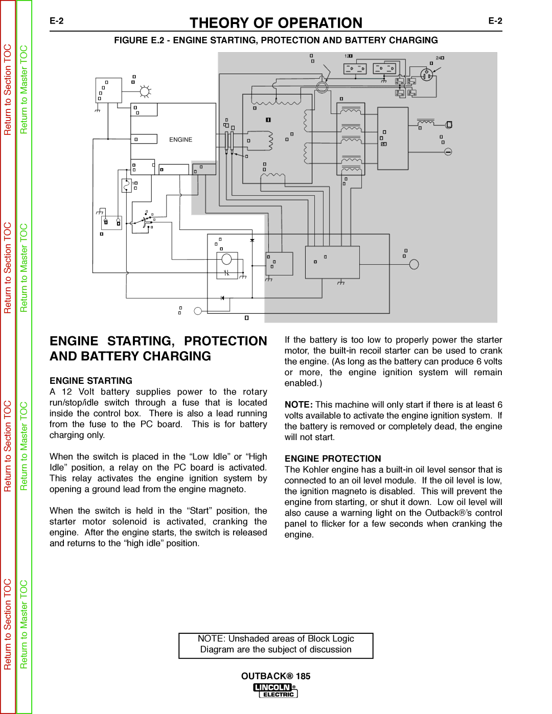
FIGURE E.2 - ENGINE STARTING, PROTECTION AND BATTERY CHARGING
|
|
|
|
|
|
| CURRENT | 120 VAC RECEPTACLES |
| 240 VAC |
|
|
|
|
|
|
| SENSOR |
|
| |
|
|
|
|
|
|
|
| RECEPTACLE | ||
|
|
|
|
|
|
|
|
| ||
|
| OIL LEVEL |
|
|
|
|
| CB1 | CB3 |
|
OIL |
| INDICATOR |
|
|
|
|
|
| ||
|
|
|
|
|
|
|
|
| ||
LEVEL |
|
|
|
|
|
|
| CB2 | CB4 |
|
MODULE |
|
|
|
|
|
|
| |||
(KOHLER) |
|
|
|
|
| REACTOR |
|
| ||
|
| OIL LEVEL |
|
| AUXIIARY WINDINGS |
|
|
|
| |
|
| SWITCH |
| RINGS |
| STATOR |
|
|
|
|
|
|
|
| SLIP |
|
|
|
|
| + |
|
|
|
| _ + |
| WELD |
| OUTPUT | CHOKE | |
|
|
|
|
|
|
|
| OUTPUT | ||
|
| IGNITION | ENGINE |
| ROTOR | WINDINGS |
| RECTIFIER |
| |
|
|
|
|
| STUDS | |||||
|
|
|
|
|
|
|
| (2 PHASE) |
| |
|
|
|
|
| BRUSHES |
|
|
|
|
|
|
| STARTER / | ALTERNATOR | IDLE | EXCITER |
|
|
|
| |
|
| SOLENOID | SOLENOID | WINDING |
|
|
|
| ||
|
|
|
|
|
|
|
|
|
| |
|
| 10 AMP |
|
|
|
|
| BOOST |
|
|
|
|
|
|
|
|
| WINDING |
|
| |
|
| FUSE |
|
|
|
|
|
|
|
|
|
| OFFAUTO |
|
|
|
|
|
|
|
|
_ | + | HIGH |
|
|
|
|
|
|
| |
START |
|
|
|
|
|
|
|
| ||
|
|
|
|
|
|
|
|
|
| |
BATTERY |
|
| ENGINE |
|
|
|
|
|
| |
|
|
|
|
|
|
|
|
|
| |
|
|
|
| SHUTDOWN |
|
|
|
|
|
|
|
|
|
| RELAY |
|
|
| OUTPUT |
| |
|
|
|
|
|
| AUTOMATIC | OUTPUT | CONTROL |
| |
|
|
|
|
|
| IDLER | CONTROL CIRCUIT |
|
| |
|
|
|
|
|
| CIRCUIT |
|
|
|
|
|
|
| HOUR |
|
|
|
|
|
|
|
|
|
| METER |
| FIELD / CONTROL PC BOARD |
|
|
| ||
|
|
|
|
|
|
|
| |||
Return to Section TOC
Return to Master TOC
ENGINE STARTING, PROTECTION AND BATTERY CHARGING
ENGINE STARTING
A 12 Volt battery supplies power to the rotary run/stop/idle switch through a fuse that is located inside the control box. There is also a lead running from the fuse to the PC board. This is for battery charging only.
When the switch is placed in the “Low Idle” or “High Idle” position, a relay on the PC board is activated. This relay activates the engine ignition system by opening a ground lead from the engine magneto.
When the switch is held in the “Start” position, the starter motor solenoid is activated, cranking the engine. After the engine starts, the switch is released and returns to the “high idle” position.
If the battery is too low to properly power the starter motor, the
NOTE: This machine will only start if there is at least 6 volts available to activate the engine ignition system. If the battery is removed or completely dead, the engine will not start.
ENGINE PROTECTION
The Kohler engine has a
Return to Section TOC
Return to Master TOC
NOTE: Unshaded areas of Block Logic Diagram are the subject of discussion