Return to Section TOC
Return to Section TOC
Return to Section TOC
Return to Section TOC
Return to Master TOC
Return to Master TOC
Return to Master TOC
Return to Master TOC
TROUBLESHOOTING AND REPAIR |
|
|
|
| ||||||
|
|
|
|
|
|
|
|
| ||
|
|
|
|
|
|
| ||||
Observe Safety Guidelines detailed in the beginning of this manual. |
|
|
|
|
|
| ||||
|
|
|
|
|
| |||||
PROBLEMS |
| POSSIBLE AREAS OF | RECOMMENDED |
|
| |||||
(SYMPTOMS) |
| MISADJUSTMENT(S) | COURSE OF ACTION |
|
| |||||
|
|
|
|
|
|
|
|
| ||
|
| OUTPUT PROBLEMS |
|
|
|
|
|
| ||
(Continued) |
|
|
|
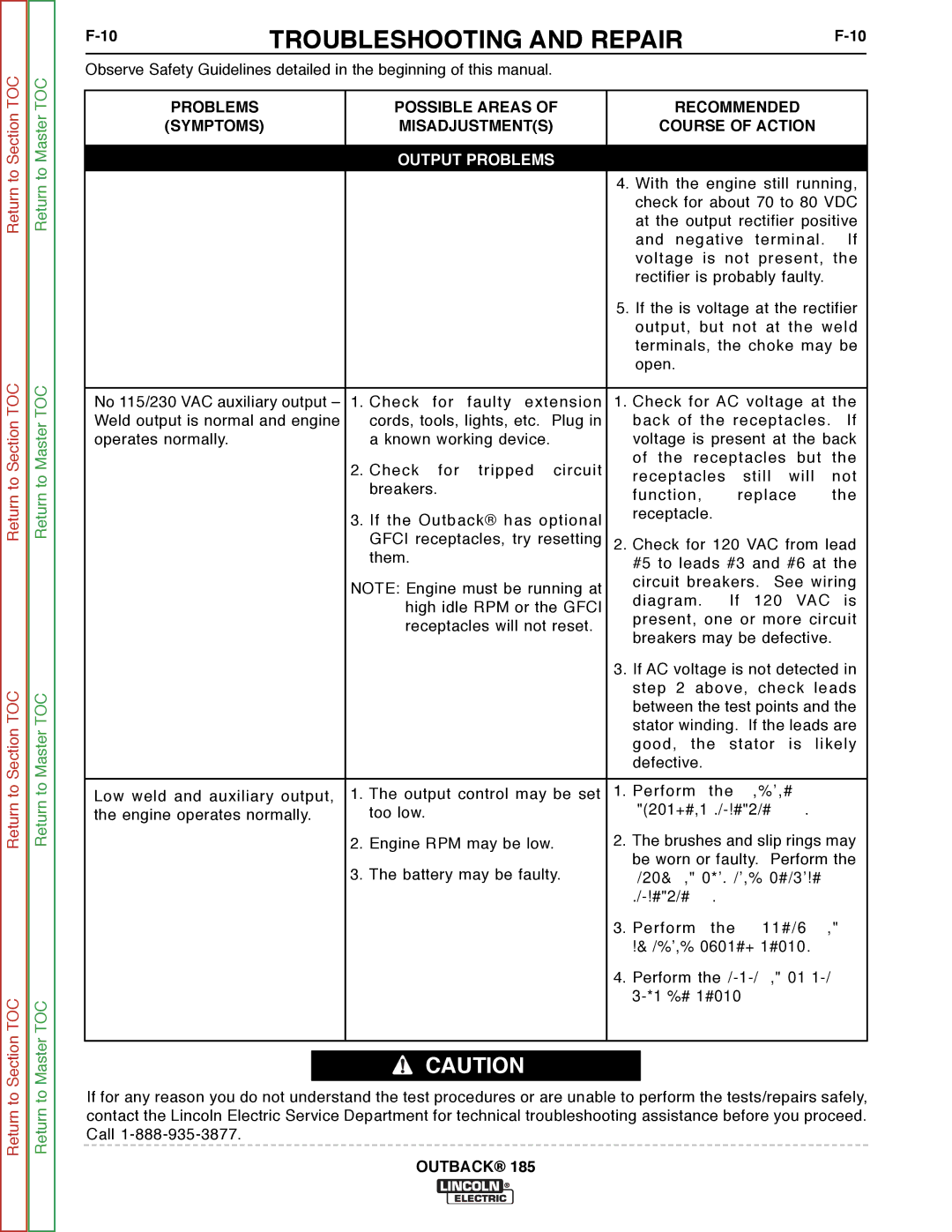
| 4. With the engine still running, | |||||
|
|
|
|
| check for about 70 to 80 VDC | |||||
|
|
|
|
| at the output rectifier positive | |||||
|
|
|
|
| and negative terminal. If | |||||
|
|
|
|
| voltage is not present, the | |||||
|
|
|
|
| rectifier is probably faulty. |
| ||||
|
|
|
|
| 5. If the is voltage at the rectifier | |||||
|
|
|
|
| output, but not at the weld | |||||
|
|
|
|
| terminals, the choke may be | |||||
|
|
|
|
| open. |
|
|
|
|
|
|
|
|
|
| ||||||
No 115/230 VAC auxiliary output – | 1. Check | for | faulty extension | 1. Check for AC voltage at the | ||||||
Weld output is normal and engine | cords, tools, lights, etc. Plug in | back of the receptacles. | If | |||||||
operates normally. |
| a known working device. | voltage is present at the back | |||||||
|
| 2. Check | for | tripped circuit | of the receptacles | but | the | |||
|
| receptacles | still | will |
| not | ||||
|
| breakers. |
|
| ||||||
|
|
| function, | replace |
| the | ||||
|
|
|
|
|
| |||||
|
| 3. If the Outback® has optional | receptacle. |
|
|
|
| |||
|
|
|
|
|
|
|
| |||
|
| GFCI receptacles, try resetting | 2. Check for 120 VAC from lead | |||||||
|
| them. |
|
| #5 to leads #3 and #6 at the | |||||
|
|
|
|
| ||||||
|
| NOTE: Engine must be running at | circuit breakers. See wiring | |||||||
|
| diagram. | If | 120 | VAC | is | ||||
|
| high idle RPM or the GFCI | ||||||||
|
| present, one or more circuit | ||||||||
|
| receptacles will not reset. | ||||||||
|
| breakers may be defective. |
| |||||||
|
|
|
|
|
| |||||
|
|
|
|
| 3. If AC voltage is not detected in | |||||
|
|
|
|
| step 2 above, check leads | |||||
|
|
|
|
| between the test points and the | |||||
|
|
|
|
| stator winding. If the leads are | |||||
|
|
|
|
| good, the stator is likely | |||||
|
|
|
|
| defective. |
|
|
|
|
|
|
|
|
|
|
| |||||
Low weld and auxiliary output, | 1. The output control may be set | 1. Perform | the | Engine | RPM | |||||
the engine operates normally. | too low. |
|
| adjustment procedure. |
|
| ||||
|
| 2. Engine RPM may be low. | 2. The brushes and slip rings may | |||||||
|
| 3. The battery may be faulty. | be worn or faulty. Perform the | |||||||
|
| brush and slip ring service | ||||||||
|
|
|
|
| procedure. |
|
|
|
| |
|
|
|
|
| 3. Perform | the | battery | and | ||
|
|
|
|
| charging system tests. |
|
| |||
|
|
|
|
| 4. Perform the rotor and stator | |||||
|
|
|
|
| voltage tests. |
|
|
|
| |
|
|
|
|
|
|
|
|
|
|
|
![]() CAUTION
CAUTION
If for any reason you do not understand the test procedures or are unable to perform the tests/repairs safely, contact the Lincoln Electric Service Department for technical troubleshooting assistance before you proceed. Call
