Return to Section TOC
Return to Section TOC
Return to Master TOC
Return to Master TOC
THEORY OF OPERATION | ||
|
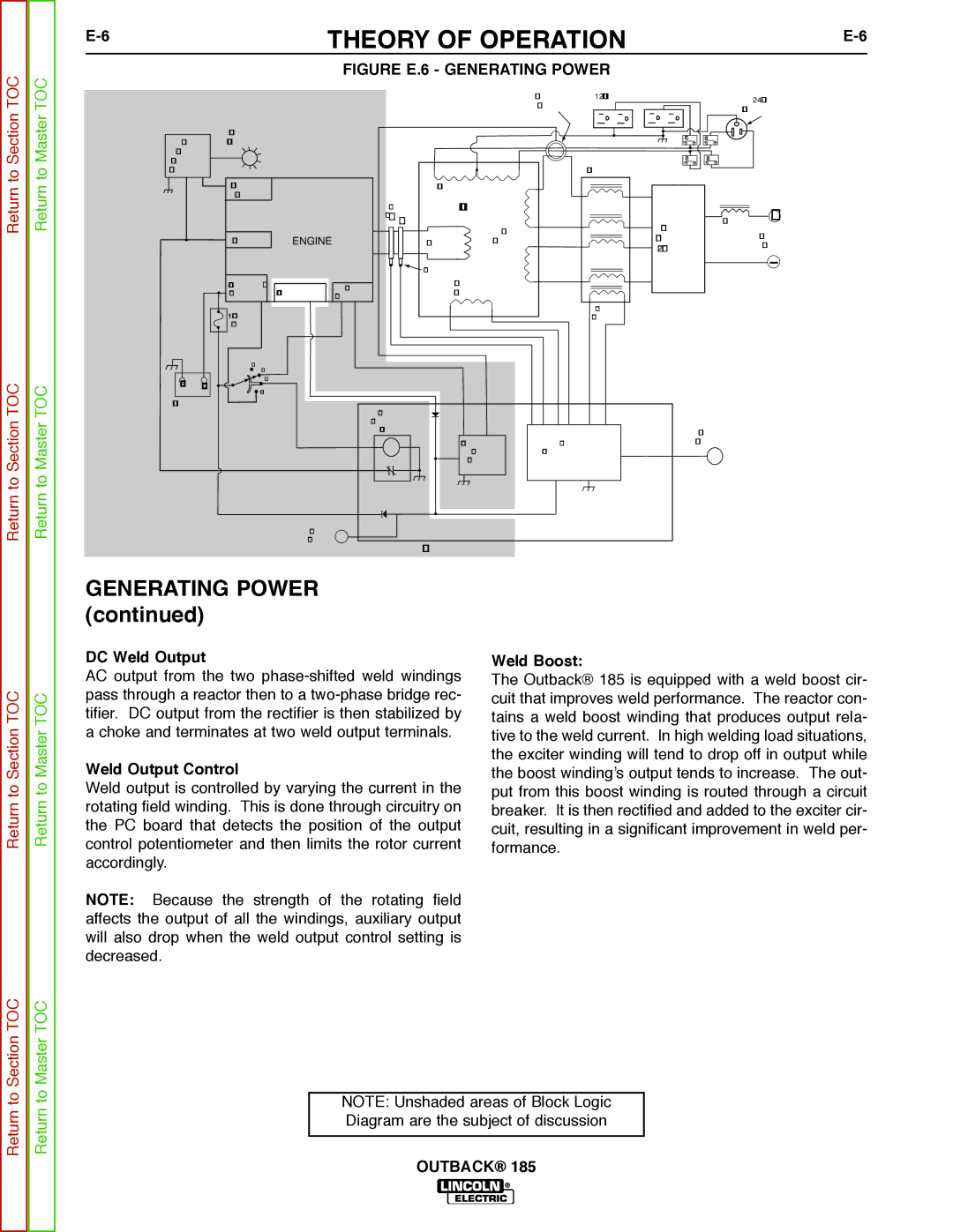
FIGURE E.6 - GENERATING POWER
|
|
|
|
|
|
| CURRENT | 120 VAC RECEPTACLES |
| 240 VAC |
|
|
|
|
|
|
| SENSOR |
|
| |
|
|
|
|
|
|
|
| RECEPTACLE | ||
|
|
|
|
|
|
|
|
| ||
|
| OIL LEVEL |
|
|
|
|
| CB1 | CB3 |
|
OIL |
| INDICATOR |
|
|
|
|
|
| ||
|
|
|
|
|
|
|
|
| ||
LEVEL |
|
|
|
|
|
|
| CB2 | CB4 |
|
MODULE |
|
|
|
|
|
|
| |||
(KOHLER) |
|
|
|
|
| REACTOR |
|
| ||
|
| OIL LEVEL |
|
| AUXIIARY WINDINGS |
|
|
|
| |
|
| SWITCH |
| RINGS |
| STATOR |
|
|
|
|
|
|
|
| SLIP |
|
|
|
|
| + |
|
|
|
| _ + |
| WELD |
| OUTPUT | CHOKE | |
|
|
|
|
|
|
|
| OUTPUT | ||
|
| IGNITION | ENGINE |
| ROTOR | WINDINGS |
| RECTIFIER |
| |
|
|
|
|
| STUDS | |||||
|
|
|
|
|
|
|
| (2 PHASE) |
| |
|
|
|
|
| BRUSHES |
|
|
|
|
|
|
| STARTER / | ALTERNATOR | IDLE | EXCITER |
|
|
|
| |
|
| SOLENOID | SOLENOID | WINDING |
|
|
|
| ||
|
|
|
|
|
|
|
|
|
| |
|
| 10 AMP |
|
|
|
|
| BOOST |
|
|
|
|
|
|
|
|
| WINDING |
|
| |
|
| FUSE |
|
|
|
|
|
|
|
|
|
| OFFAUTO |
|
|
|
|
|
|
|
|
_ | + | HIGH |
|
|
|
|
|
|
| |
START |
|
|
|
|
|
|
|
| ||
|
|
|
|
|
|
|
|
|
| |
BATTERY |
|
| ENGINE |
|
|
|
|
|
| |
|
|
|
|
|
|
|
|
|
| |
|
|
|
| SHUTDOWN |
|
|
|
|
|
|
|
|
|
| RELAY |
|
|
| OUTPUT |
| |
|
|
|
|
|
| AUTOMATIC | OUTPUT | CONTROL |
| |
|
|
|
|
|
| IDLER | CONTROL CIRCUIT |
|
| |
|
|
|
|
|
| CIRCUIT |
|
|
|
|
|
|
| HOUR |
|
|
|
|
|
|
|
|
|
| METER |
| FIELD / CONTROL PC BOARD |
|
|
| ||
|
|
|
|
|
|
|
| |||
Return to Section TOC
Return to Master TOC
GENERATING POWER (continued)
DC Weld Output
AC output from the two
Weld Output Control
Weld output is controlled by varying the current in the rotating field winding. This is done through circuitry on the PC board that detects the position of the output control potentiometer and then limits the rotor current accordingly.
NOTE: Because the strength of the rotating field affects the output of all the windings, auxiliary output will also drop when the weld output control setting is decreased.
Weld Boost:
The Outback® 185 is equipped with a weld boost cir- cuit that improves weld performance. The reactor con- tains a weld boost winding that produces output rela- tive to the weld current. In high welding load situations, the exciter winding will tend to drop off in output while the boost winding’s output tends to increase. The out- put from this boost winding is routed through a circuit breaker. It is then rectified and added to the exciter cir- cuit, resulting in a significant improvement in weld per- formance.
Return to Section TOC
Return to Master TOC
NOTE: Unshaded areas of Block Logic Diagram are the subject of discussion