INSTALLATION | ||
|
|
Return to Section TOC
Return to Section TOC
Return to Section TOC
Return to Master TOC
Return to Master TOC
Return to Master TOC
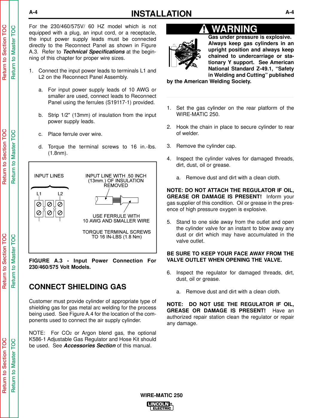
For the 230/460/575V/ 60 HZ model which is not equipped with a plug, an input cord, or a receptacle, the input power supply leads must be connected directly to the Reconnect Panel as shown in Figure A.3. Refer to Technical Specifications at the begin- ning of this chapter for proper wire sizes.
1.Connect the input power leads to terminals L1 and L2 on the Reconnect Panel Assembly.
a.For input power supply leads of 10 AWG or smaller are used, connect leads to Reconnect Panel using the ferrules
b.Strip 1/2" (13mm) of insulation from the input power supply leads.
c.Place ferrule over wire.
d.Torque the terminal screws to 16
FIGURE A.3 - Input Power Connection For 230/460/575 Volt Models.
![]() WARNING
WARNING
Gas under pressure is explosive. Always keep gas cylinders in an
upright position and always keep
chained to undercarriage or sta-
tionary Y support. See American National Standard Z-49.1, “Safety in Welding and Cutting” published
by the American Welding Society.
____________________________________
1.Set the gas cylinder on the rear platform of the
2.Hook the chain in place to secure cylinder to rear of welder.
3.Remove the cylinder cap.
4.Inspect the cylinder valves for damaged threads, dirt, dust, oil or grease.
a. Remove dust and dirt with a clean cloth.
NOTE: DO NOT ATTACH THE REGULATOR IF OIL, GREASE OR DAMAGE IS PRESENT! Inform your gas supplier of this condition. Oil or grease in the pres- ence of high pressure oxygen is explosive.
5.Stand to one side away from the outlet and open the cylinder valve for an instant to blow away any dust or dirt which may have accumulated in the valve outlet.
BE SURE TO KEEP YOUR FACE AWAY FROM THE VALVE OUTLET WHEN OPENING THE VALVE.
6.Inspect the regulator for damaged threads, dirt, dust, oil or grease.
Return to Section TOC
Return to Master TOC
CONNECT SHIELDING GAS
Customer must provide cylinder of appropriate type of shielding gas for gas metal arc welding for the process being used. See Figure A.4 for the location of the com- ponents used to connect the air supply cylinder.
NOTE: For CO2 or Argon blend gas, the optional
a. Remove dust and dirt with a clean cloth.
NOTE: DO NOT USE THE REGULATOR IF OIL, GREASE OR DAMAGE IS PRESENT! Have an authorized repair station clean the regulator or repair any damage.