Return to Section TOC
Return to Section TOC
Return to Section TOC
Return to Section TOC
Return to Master TOC
Return to Master TOC
Return to Master TOC
Return to Master TOC
TROUBLESHOOTING & REPAIR | ||
|
|
STATIC SCR RECTIFIER ASSEMBLY TEST (CONTINUED)
NOTE: DO NOT DISASSEMBLE THE
SCR RECTIFIER HEAT SINK ASSEM-
BLY.
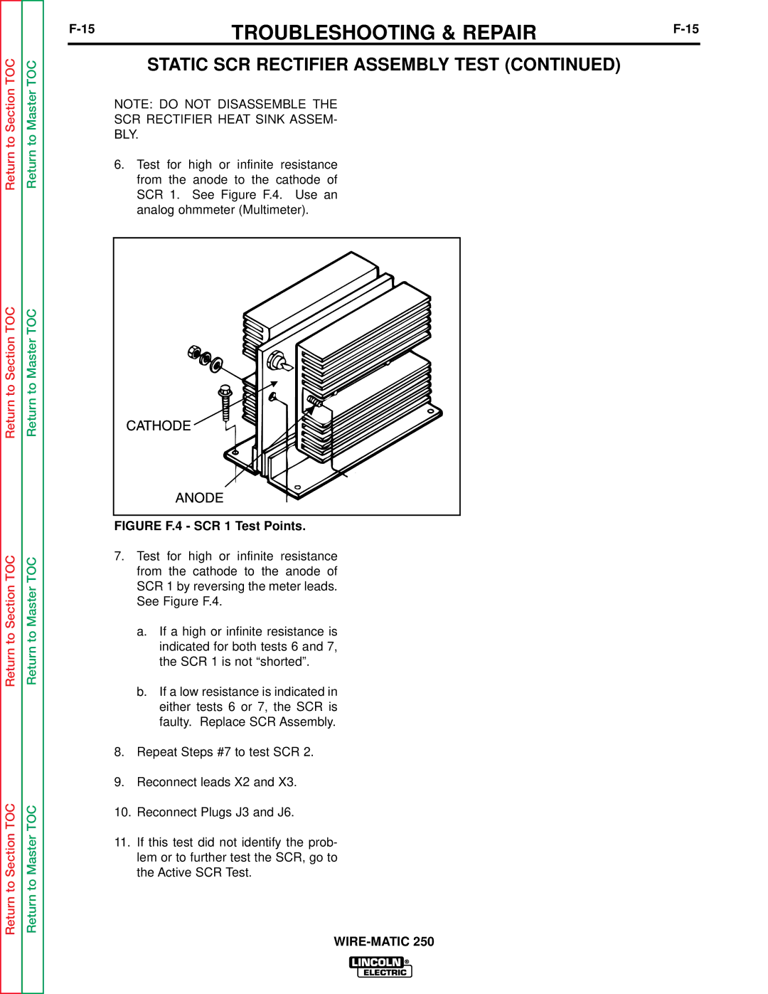
6.Test for high or infinite resistance from the anode to the cathode of SCR 1. See Figure F.4. Use an analog ohmmeter (Multimeter).
FIGURE F.4 - SCR 1 Test Points.
7.Test for high or infinite resistance from the cathode to the anode of SCR 1 by reversing the meter leads. See Figure F.4.
a.If a high or infinite resistance is indicated for both tests 6 and 7, the SCR 1 is not “shorted”.
b.If a low resistance is indicated in either tests 6 or 7, the SCR is faulty. Replace SCR Assembly.
8.Repeat Steps #7 to test SCR 2.
9.Reconnect leads X2 and X3.
10.Reconnect Plugs J3 and J6.
11.If this test did not identify the prob- lem or to further test the SCR, go to the Active SCR Test.