|
| TROUBLESHOOTING & REPAIR | |||
|
|
|
| ||
TOC | TOC | SCR OUTPUT RECTIFIER REMOVAL & REPLACEMENT (CONTINUED) | |||
|
|
|
| ||
Section | Master | PROCEDURE | 4. Cut the SCR gate leads G1 and G2 |
| |
|
|
|
| (see wire markers and wiring dia- |
|
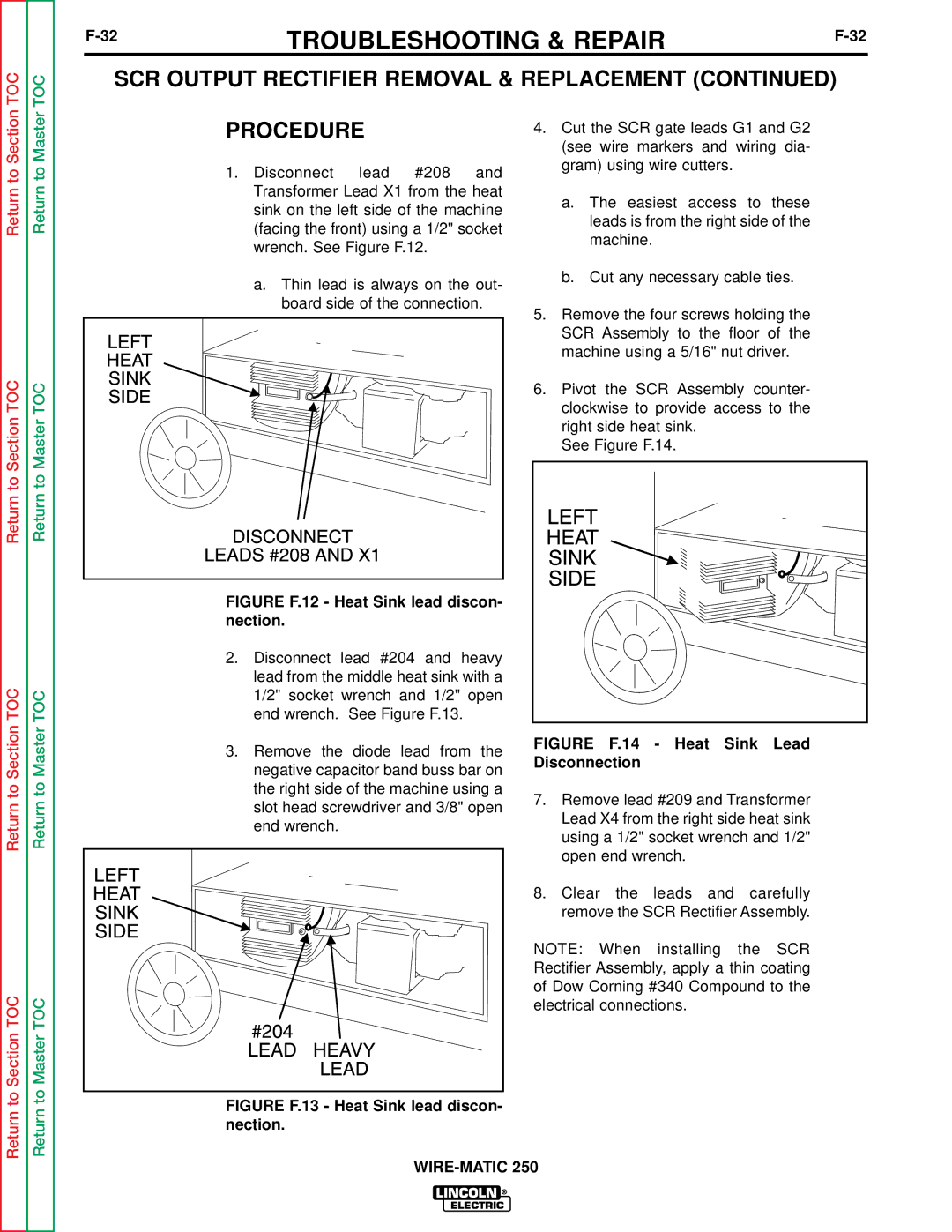
to | to | 1. | Disconnect lead #208 and | gram) using wire cutters. |
|
|
| ||||
|
|
|
| ||
Return | Return |
| Transformer Lead X1 from the heat | leads is from the right side of the |
|
| (facing the front) using a 1/2" socket |
| |||
|
|
| sink on the left side of the machine | a. The easiest access to these |
|
|
|
|
|
| |
|
|
| wrench. See Figure F.12. | machine. |
|
|
|
|
|
| |
|
|
| a. Thin lead is always on the out- | b. Cut any necessary cable ties. |
|
|
|
|
|
| |
|
|
| board side of the connection. |
|
|
|
|
| 5. Remove the four screws holding the | ||||||
|
|
| SCR Assembly to the floor of the | ||||||
|
|
| machine using a 5/16" nut driver. | ||||||
TOC | TOC |
| 6. Pivot the SCR Assembly counter- | ||||||
| clockwise to provide access to the | ||||||||
SectiontoReturn | MastertoReturn |
| right side heat sink. |
|
| ||||
|
|
|
|
| |||||
|
|
| See Figure F.14. |
|
| ||||
|
| FIGURE F.12 - Heat Sink lead discon- |
|
|
|
|
|
| |
|
| nection. |
|
|
|
|
|
| |
|
| 2. Disconnect lead #204 and heavy |
|
|
|
|
|
| |
TOC |
| lead from the middle heat sink with a |
|
|
|
|
|
| |
TOC | 1/2" socket wrench and 1/2" open |
|
|
|
|
|
| ||
end wrench. See Figure F.13. |
|
|
|
|
|
| |||
Section | Master | negative capacitor band buss bar on | Disconnection | - | Heat | Sink | Lead | ||
|
| 3. Remove the diode lead from the | FIGURE | F.14 | |||||
|
|
|
|
|
|
|
| ||
to | to | the right side of the machine using a | 7. Remove lead #209 and Transformer | ||||||
Return | Return | slot head screwdriver and 3/8" open | |||||||
Lead X4 from the right side heat sink | |||||||||
|
| ||||||||
|
| end wrench. | |||||||
|
| using a 1/2" socket wrench and 1/2" | |||||||
|
|
| |||||||
|
|
| open end wrench. |
|
| ||||
|
|
| 8. Clear the leads and carefully | ||||||
|
|
| remove the SCR Rectifier Assembly. | ||||||
|
|
| NOTE: When installing the SCR | ||||||
|
|
| Rectifier Assembly, apply a thin coating | ||||||
TOCSectionto | TOCMasterto |
| of Dow Corning #340 Compound to the | ||||||
| electrical connections. |
|
| ||||||
|
|
|
|
| |||||
Return | Return | FIGURE F.13 - Heat Sink lead discon- |
|
|
|
|
|
| |
nection. |
|
|
|
|
|
| |||
|
|
|
|
|
|
|
| ||
|
|
|
|
|
|
|
| ||