Return to Section TOC
Return to Section TOC
Return to Section TOC
Return to Master TOC
Return to Master TOC
Return to Master TOC
OPERATION | ||
|
|
CONTROLS AND SETTINGS
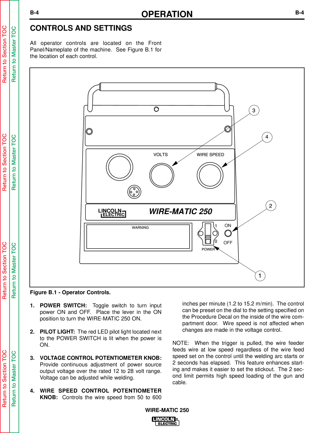
All operator controls are located on the Front Panel/Nameplate of the machine. See Figure B.1 for the location of each control.
ELECTRIC |
|
LINCOLN |
|
ON
OFF
Figure B.1 - Operator Controls.
Return to Section TOC
Return to Master TOC
1.POWER SWITCH: Toggle switch to turn input power ON and OFF. Place the lever in the ON position to turn the
2.PILOT LIGHT: The red LED pilot light located next to the POWER SWITCH is lit when the power is ON.
3.VOLTAGE CONTROL POTENTIOMETER KNOB: Provide continuous adjustment of power source output voltage over the rated 12 to 28 volt range. Voltage can be adjusted while welding.
4.WIRE SPEED CONTROL POTENTIOMETER KNOB: Controls the wire speed from 50 to 600
inches per minute (1.2 to 15.2 m/min). The control can be preset on the dial to the setting specified on the Procedure Decal on the inside of the wire com- partment door. Wire speed is not affected when changes are made in the voltage control.
NOTE: When the trigger is pulled, the wire feeder feeds wire at low speed regardless of the wire feed speed set on the control until the welding arc starts or 2 seconds has elapsed. This feature enhances start- ing and makes it easier to set the stickout. The 2 sec- ond limit permits high speed loading of the gun and cable.