THEORY OF OPERATION | ||
|
|
to Section TOC | to Master TOC |
| CONSTANT VOLTAGE OUTPUT | ||||
|
|
|
|
|
| ||
Return | Return |
| WIRE | GAS |
|
|
|
| SPEED | SOLENOID |
|
| |||
|
|
|
|
| WIRE | ||
|
|
|
|
|
|
| DRIVE |
|
|
| ARC |
|
|
| MOTOR |
|
|
| VOLTAGE |
|
|
|
|
|
|
| CONTROL BOARD |
|
|
| |
|
|
|
| G |
|
| TACH |
|
|
|
|
|
|
| |
|
|
|
| A |
|
|
|
|
|
|
| T |
| GUN TRIGGER AND THUMB SWITCH | |
|
| LINE | MAIN | E |
| ||
|
| S |
|
|
| ||
|
| TRANSFORMER |
|
|
| ||
|
| SWITCH | I |
|
| FEEDBACK | |
|
|
|
| G |
|
| |
|
|
|
| N |
|
|
|
TOC |
|
|
| A |
|
|
|
TOC |
|
| L |
|
|
| |
| RECONNECT |
|
|
| POSITIVE | ||
|
|
|
|
| |||
Section | Master |
|
|
|
|
| |
|
|
|
|
| TERMINAL | ||
|
|
| C |
| CHOKE | ||
|
|
|
|
| |||
|
|
| A | F |
| ||
|
|
| P | E |
| ||
|
|
| A | E |
| ||
to | to |
|
|
|
| ||
|
|
| C | D |
| ||
| SCR | I | B |
| |||
Return | Return |
| RECTIFIER | T | A |
| |
|
|
| O | C |
| ||
| FAN |
| R | K | NEGATIVE | ||
|
| S |
| ||||
| MOTORS |
|
| TERMINAL | |||
|
|
|
| ||||
|
|
|
|
|
| ||
|
|
|
|
|
| SHUNT |
|
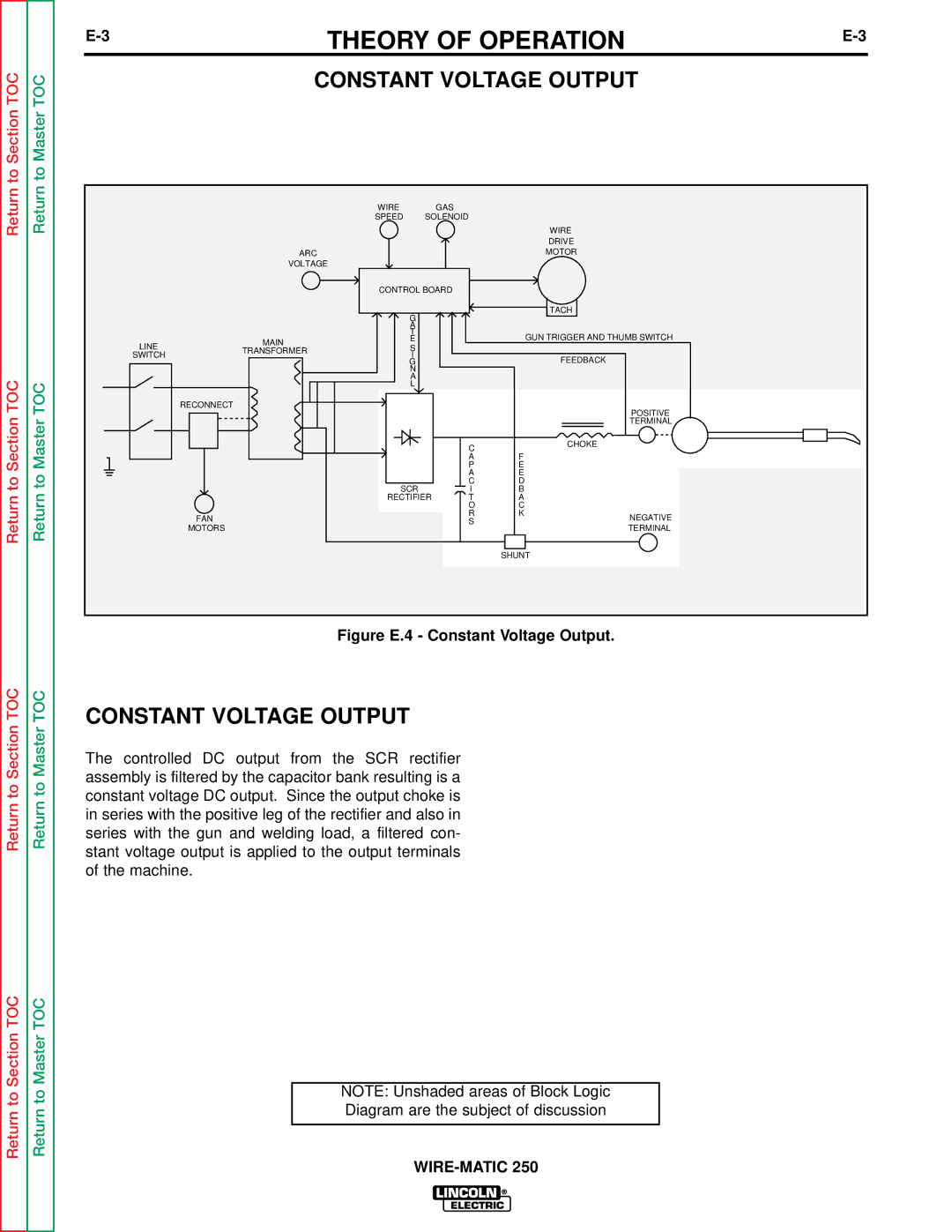
Figure E.4 - Constant Voltage Output.
TOC | TOC | CONSTANT VOLTAGE OUTPUT | |
Section | Master | ||
The controlled DC output from the SCR rectifier | |||
|
| ||
to | to | assembly is filtered by the capacitor bank resulting is a | |
constant voltage DC output. Since the output choke is | |||
Return | Return | ||
in series with the positive leg of the rectifier and also in | |||
|
| ||
|
| series with the gun and welding load, a filtered con- | |
|
| stant voltage output is applied to the output terminals | |
|
| of the machine. |
Section TOC | Master TOC |
| |
to | to | NOTE: Unshaded areas of Block Logic | |
Diagram are the subject of discussion | |||
Return | Return | ||
| |||
|
|
