INSTALLATION | ||
|
|
Return to Section TOC
Return to Section TOC
Return to Section TOC
Return to Master TOC
Return to Master TOC
Return to Master TOC
Read entire Installation Section before installing the
SAFETY PRECAUTIONS
![]() WARNING
WARNING
ELECTRIC SHOCK can kill.
• Only qualified personnel should install this machine.
•Turn the input power OFF at the dis- connect switch or fuse box before working on the equipment.
•Do not touch electrically hot parts.
•Always connect the
•Set the
____________________________________
SELECT PROPER LOCATION
Place the
INPUT CONNECTIONS
![]() WARNING
WARNING
All input power must be electrically disconnected before proceeding.
____________________________________
1.Before starting the installation, check with the local power company to determine if there is any ques- tion about whether your power supply is adequate for the voltage, amperes, phase, and frequency specified on the welder nameplate. Be sure the planned installation will meet the U.S. National Electrical Code and local code requirements. This welder may be operated from a single phase line or from one phase of a two or three phase line.
2.Models that have multiple input voltages specified on the nameplate (e.g., 208/230) are shipped con- nected for the highest voltage. If the welder is to be operated at a lower voltage, it must be recon- nected according to the instructions on the inside of the removable panel (Reconnect Access Door) near the top left side of the Case Back Assembly. See the Reconnect Section of this manual for details on reconnecting the machine to operate at different voltages.
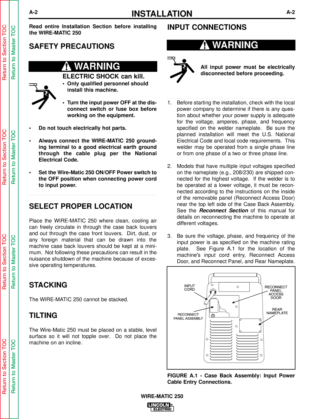
3.Be sure the voltage, phase, and frequency of the input power is as specified on the machine rating plate. See Figure A.1 for the location of the machine's input cord entry, Reconnect Access Door, and Reconnect Panel, and Rear Nameplate.
Return to Section TOC
Return to Master TOC
STACKING
The
TILTING
The