Return to Master
REMOVAL AND REPLACE- MENT PROCEDURE
1.Disconnect main input power the machine.
2.Remove the Case Top and Side Panels using 5/16" nut driver.
3.Disconnect all wiring harness plugs and Molex Plugs connected to the Control Board. See Figure F.9.
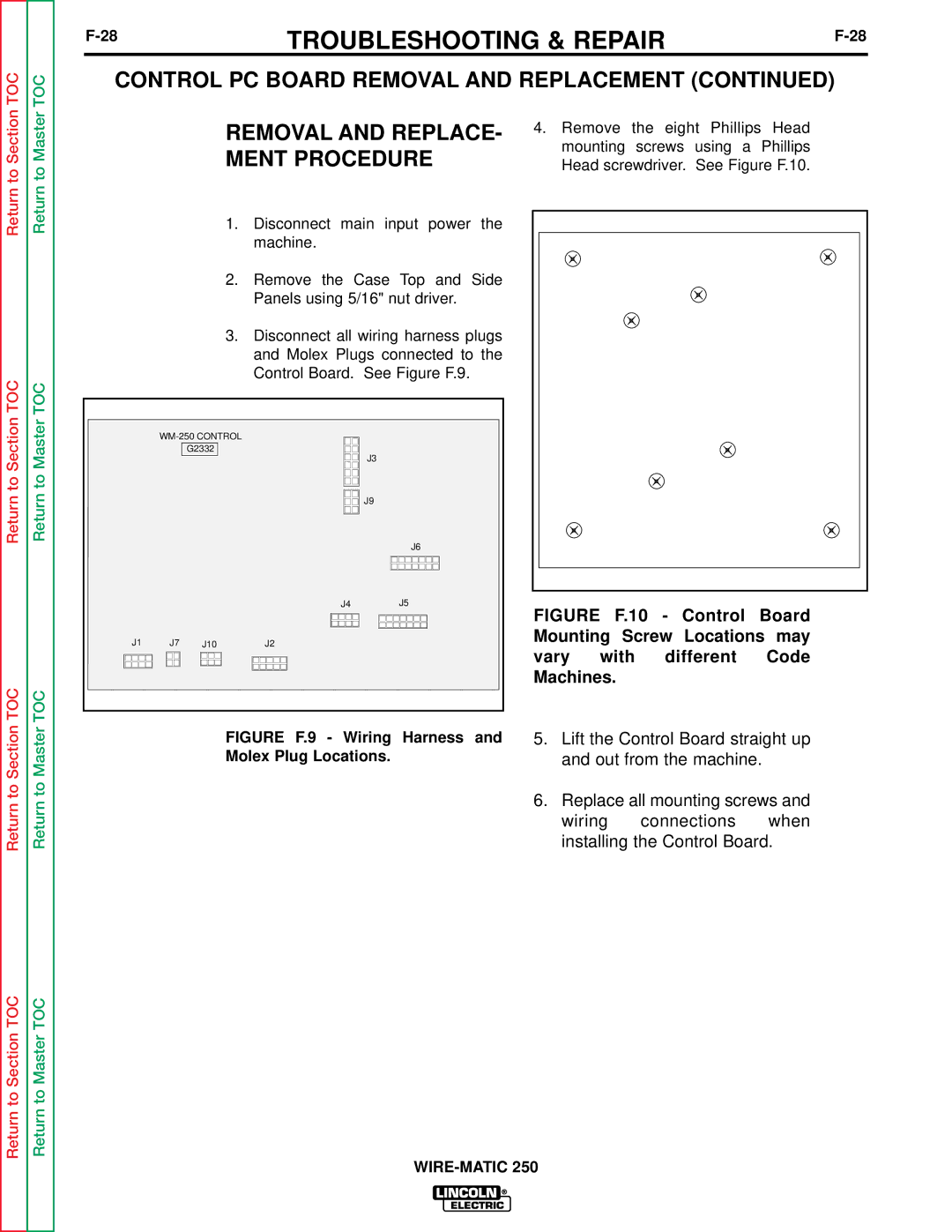
4.Remove the eight Phillips Head mounting screws using a Phillips Head screwdriver. See Figure F.10.
Return to Section TOC
Return to Master TOC
G2332
J3
J9
J6
J4J5
J1 | J7 |
| J10 | J2 | ||
|
|
|
|
|
|
|
|
|
|
|
|
|
|
|
|
|
|
|
|
|
FIGURE F.10 - Control Board Mounting Screw Locations may
vary with different Code Machines.
Return to Section TOC
Return to Section TOC
Return to Master TOC
Return to Master TOC
FIGURE F.9 - Wiring Harness and Molex Plug Locations.
5.Lift the Control Board straight up and out from the machine.
6.Replace all mounting screws and wiring connections when installing the Control Board.