TROUBLESHOOTING & REPAIR | ||
|
|
TOC | TOC | CAPACITOR BANK REMOVAL AND REPLACEMENT (CONTINUED) | |||
|
|
| |||
Section | Master | PROCEDURE | 6. Remove the #204 lead from the pos- | ||
|
| itive buss bar. | |||
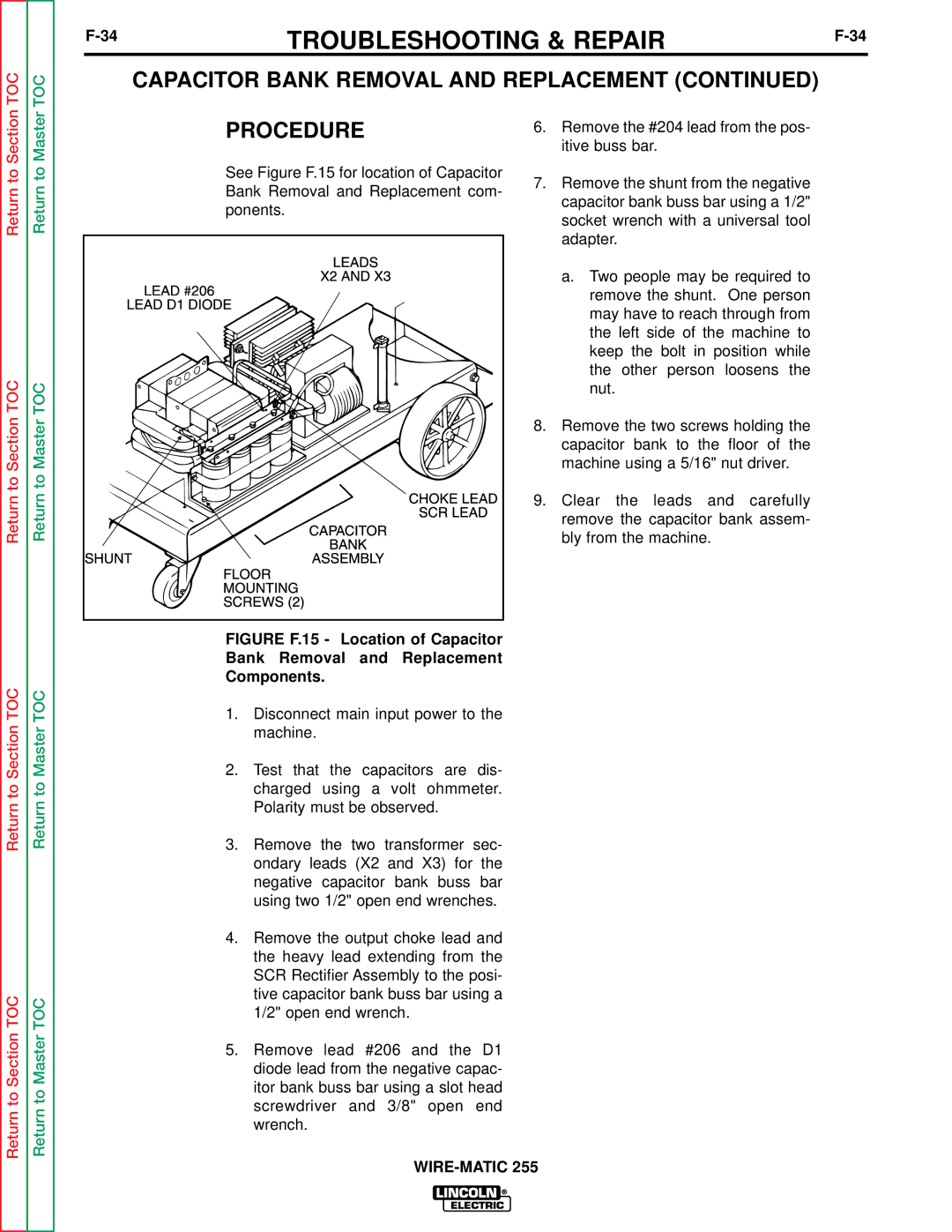
See Figure F.15 for location of Capacitor |
|
| |||
to | to | 7. | Remove the shunt from the negative | ||
Bank Removal and Replacement com- | |||||
Return | Return | ||||
| capacitor bank buss bar using a 1/2" | ||||
ponents. |
| ||||
| socket wrench with a universal tool | ||||
|
| ||||
|
| adapter. | |||
|
|
|
| ||
|
|
|
| a. Two people may be required to | |
|
|
|
| remove the shunt. One person | |
|
|
|
| may have to reach through from | |
|
|
|
| the left side of the machine to | |
|
|
|
| keep the bolt in position while | |
TOC |
|
|
| the other person loosens the | |
TOC |
|
| nut. | ||
|
|
| |||
Section | Master |
| 8. Remove the two screws holding the | ||
|
| capacitor bank to the floor of the | |||
|
| machine using a 5/16" nut driver. | |||
to | to |
|
|
| |
Return | Return |
| 9. Clear the leads and carefully | ||
|
| remove the capacitor bank assem- | |||
|
| bly from the machine. | |||
|
| FIGURE F.15 - Location of Capacitor | |||
|
| Bank Removal | and Replacement | ||
TOC |
| Components. |
| ||
TOC | 1. Disconnect main input power to the | ||||
Section | Master | 2. | Test that the capacitors are dis- | ||
|
|
| machine. |
| |
to | to | 3. | charged using a volt ohmmeter. | ||
Return | Return | Remove the | two transformer sec- | ||
|
|
| Polarity must be observed. | ||
|
|
| ondary leads (X2 and X3) for the | ||
|
|
| negative capacitor bank buss bar | ||
|
|
| using two 1/2" open end wrenches. | ||
|
| 4. Remove the output choke lead and | |||
|
|
| the heavy lead extending from the | ||
|
|
| SCR Rectifier Assembly to the posi- | ||
TOC | TOC |
| tive capacitor bank buss bar using a | ||
| 1/2" open end wrench. | ||||
Section | Master |
| |||
5. Remove lead #206 and the D1 | |||||
|
| ||||
|
|
| diode lead from the negative capac- | ||
to | to |
| itor bank buss bar using a slot head | ||
| screwdriver | and 3/8" open end | |||
Return | Return |
| |||
| wrench. |
| |||
|
|
|
| ||
|
|
|
|
| |
