OPERATION | ||
|
|
Return to Section TOC
Return to Section TOC
to Section TOC
Return to Master TOC
Return to Master TOC
to Master TOC
USING THE WIRE DRIVE ROLL
The drive roll provided with the
PROCEDURE FOR CHANGING DRIVE ROLL
Different wire sizes may require changing the drive roll. The applicable wire sizes are stamped on the drive roll. Dual groove rolls must be installed so the side with the proper wire size stamp faces out.
1.Turn POWER SWITCH to OFF.
2.Release the pressure on the idle roll by swinging the pressure arm off the idle roll arm.
3.Remove the wire from the drive system.
4.Remove the thumb screw from the drive roll.
5.Turn the drive roll over or change to another roll as required.
6.Replace the thumb screw.
7.Check that the gun liner and contact tip are prop- erly sized for wire being used.
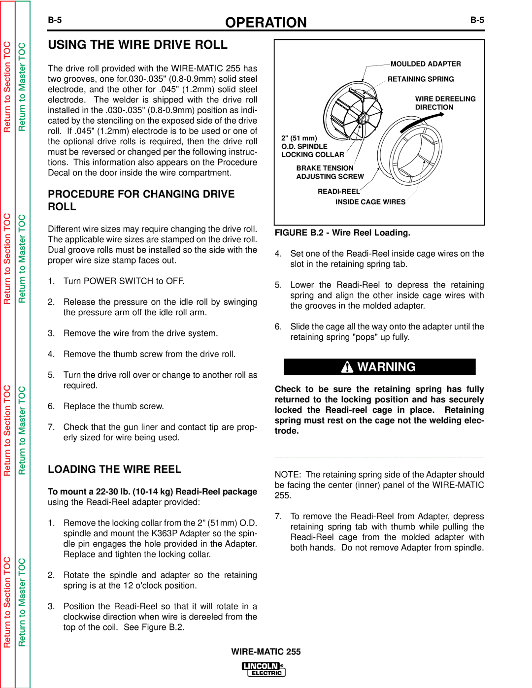
![]() MOULDED ADAPTER
MOULDED ADAPTER
RETAINING SPRING
WIRE DEREELING
DIRECTION
2" (51 mm)
O.D. SPINDLE LOCKING COLLAR
BRAKE TENSION
ADJUSTING SCREW
INSIDE CAGE WIRES
FIGURE B.2 - Wire Reel Loading.
4.Set one of the
5.Lower the
6.Slide the cage all the way onto the adapter until the retaining spring "pops" up fully.
![]() WARNING
WARNING
Check to be sure the retaining spring has fully returned to the locking position and has securely locked the
Return
Return to Section TOC
Return
Return to Master TOC
LOADING THE WIRE REEL
To mount a
1.Remove the locking collar from the 2” (51mm) O.D. spindle and mount the K363P Adapter so the spin- dle pin engages the hole provided in the Adapter. Replace and tighten the locking collar.
2.Rotate the spindle and adapter so the retaining spring is at the 12 o'clock position.
3.Position the
____________________________________
NOTE: The retaining spring side of the Adapter should be facing the center (inner) panel of the
7.To remove the