THEORY OF OPERATION | ||
|
|
to Section TOC | to Master TOC |
| INPUT LINE VOLTAGE AND MAIN TRANSFORMER | ||||
|
|
|
|
|
| ||
Return | Return |
| WIRE | GAS |
|
|
|
| SPEED | SOLENOID |
|
| |||
|
|
|
|
| WIRE | ||
|
|
|
|
|
|
| DRIVE |
|
|
| ARC |
|
|
| MOTOR |
|
|
| VOLTAGE |
|
|
|
|
|
|
| CONTROL BOARD |
|
|
| |
|
|
|
| G |
|
| TACH |
|
|
|
|
|
|
| |
|
|
|
| A |
|
|
|
|
|
|
| T |
| GUN TRIGGER AND THUMB SWITCH | |
|
| LINE | MAIN | E |
| ||
|
| S |
|
|
| ||
|
| TRANSFORMER |
|
|
| ||
|
| SWITCH | I |
|
| FEEDBACK | |
|
|
|
| G |
|
| |
|
|
|
| N |
|
|
|
TOC |
|
|
| A |
|
|
|
TOC |
|
| L |
|
|
| |
| RECONNECT |
|
|
| POSITIVE | ||
|
|
|
|
| |||
Section | Master |
|
|
|
|
| |
|
|
|
|
| TERMINAL | ||
|
|
| C |
| CHOKE | ||
|
|
|
|
| |||
|
|
| A | F |
| ||
|
|
| P | E |
| ||
|
|
| A | E |
| ||
to | to |
|
|
|
| ||
|
|
| C | D |
| ||
| SCR | I | B |
| |||
Return | Return |
| RECTIFIER | T | A |
| |
|
|
| O | C |
| ||
| FAN |
| R | K | NEGATIVE | ||
|
| S |
| ||||
| MOTORS |
|
| TERMINAL | |||
|
|
|
| ||||
|
|
|
|
|
| ||
|
|
|
|
|
| SHUNT |
|
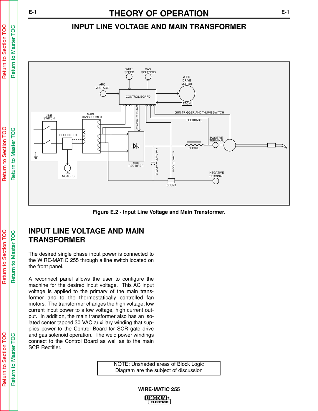
Figure E.2 - Input Line Voltage and Main Transformer.
TOC | TOC | INPUT LINE VOLTAGE AND MAIN | ||
TRANSFORMER | ||||
Section | Master | |||
The desired single phase input power is connected to | ||||
|
| |||
to | to | the | ||
the front panel. | ||||
Return | Return | |||
A reconnect panel allows the user to configure the | ||||
|
| |||
|
| machine for the desired input voltage. This AC input | ||
|
| voltage is applied to the primary of the main trans- | ||
|
| former and to the thermostatically controlled fan | ||
|
| motors. The transformer changes the high voltage, low | ||
|
| current input power to a low voltage, high current out- | ||
|
| put. In addition, the main transformer also has an iso- | ||
|
| lated center tapped 30 VAC auxiliary winding that sup- | ||
TOC |
| plies power to the Control Board for SCR gate drive | ||
TOC | and gas solenoid operation. The weld power windings | |||
connect to the Control Board as well as to the main | ||||
Section | Master | SCR Rectifier. | ||
|
| |||
|
|
|
| |
to | to |
| NOTE: Unshaded areas of Block Logic | |
| Diagram are the subject of discussion | |||
Return | Return |
| ||
|
| |||
|
| |||
|
|
| ||