PROCEDURE
1.Disconnect main input power to the machine.
2.Remove the Case Top and Side Panels.
3.Using the 5/16” Nutdriver remove the gear box top cover.
4.Remove the two sheet metal screws located on the left rear side of the gear box housing using a 5/16” nut- driver.
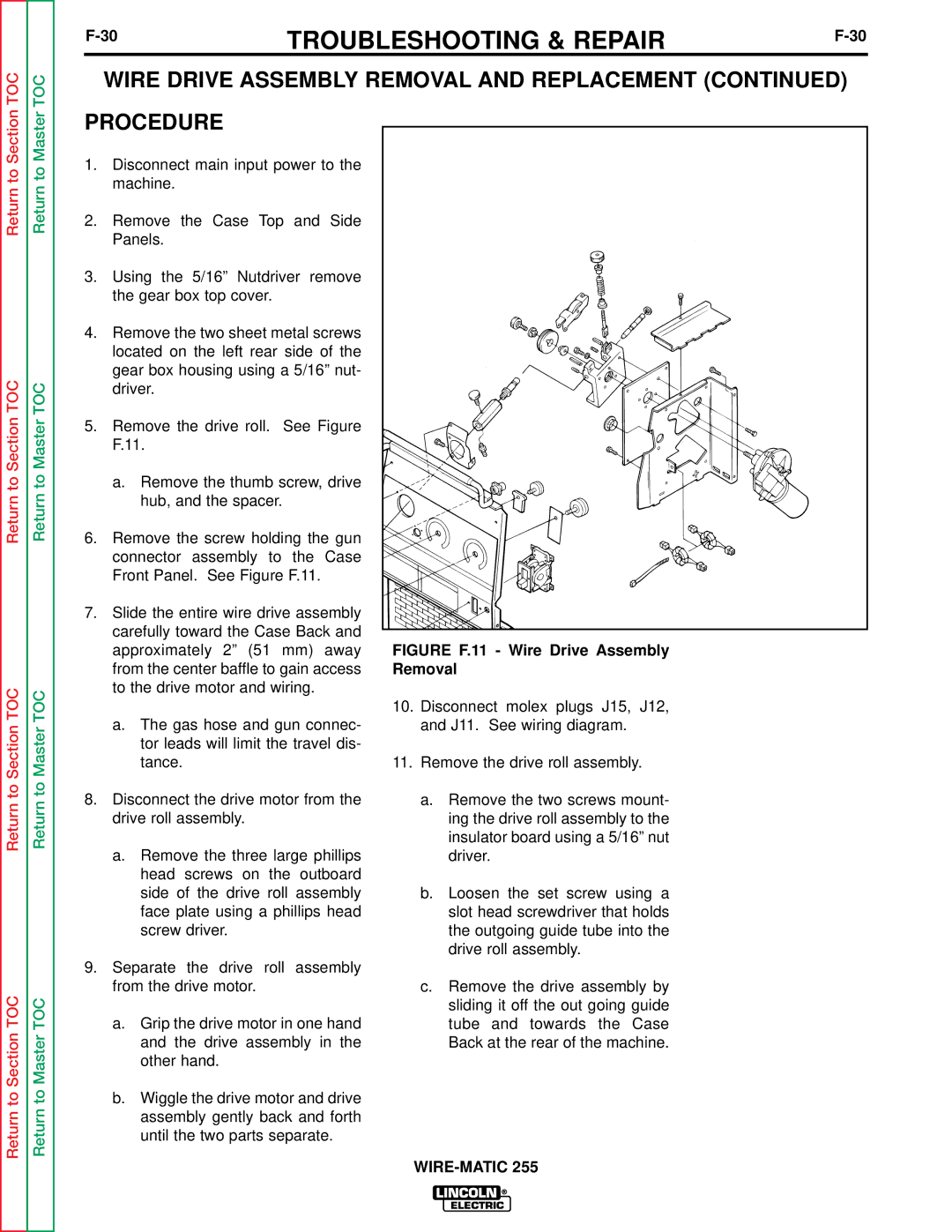
5.Remove the drive roll. See Figure F.11.
a.Remove the thumb screw, drive hub, and the spacer.
6.Remove the screw holding the gun connector assembly to the Case Front Panel. See Figure F.11.
7.Slide the entire wire drive assembly carefully toward the Case Back and approximately 2” (51 mm) away from the center baffle to gain access to the drive motor and wiring.
a.The gas hose and gun connec- tor leads will limit the travel dis- tance.
8.Disconnect the drive motor from the drive roll assembly.
a.Remove the three large phillips head screws on the outboard side of the drive roll assembly face plate using a phillips head screw driver.
9.Separate the drive roll assembly from the drive motor.
a.Grip the drive motor in one hand and the drive assembly in the other hand.
b.Wiggle the drive motor and drive assembly gently back and forth until the two parts separate.
FIGURE F.11 - Wire Drive Assembly Removal
10.Disconnect molex plugs J15, J12, and J11. See wiring diagram.
11.Remove the drive roll assembly.
a.Remove the two screws mount- ing the drive roll assembly to the insulator board using a 5/16” nut driver.
b.Loosen the set screw using a slot head screwdriver that holds the outgoing guide tube into the drive roll assembly.
c.Remove the drive assembly by sliding it off the out going guide tube and towards the Case Back at the rear of the machine.