INSTALLATION | ||
|
|
Return to Section TOC
Return to Section TOC
Return to Section TOC
Return to Section TOC
Return to Master TOC
Return to Master TOC
Return to Master TOC
Return to Master TOC
FUSE AND WIRE SIZES
Protect the input circuit with the super lag fuses or delay type circuit breakers listed on the Technical Specifications page of this manual for the machine being used. The tripping action of delay type circuit breakers decreases as the magnitude of the current increases. They are also called inverse time or ther- mal/magnetic circuit breakers.
DO NOT use fuses or circuit breakers with a lower amp rating than recommended. This can result in "nui- sance" tripping caused by inrush current even when machine is not being used for welding at high output currents.
Use input and grounding wire sizes that meet local electrical codes or see the Technical Specifications page in this manual.
INPUT POWER CONNECTIONS AND GROUND CONNECTIONS
Have a qualified electrician connect the receptacle or cable to the input power lines and the system ground according to the U.S. National Electrical Code and any applicable local codes.
1.Follow the Input Supply Connection Diagram on the inside of the Reconnect Panel Access Door.
2.Use a
For the 208V/230V/ 60 HZ model
1.Mount the receptacle in a suitable location using the screws provided.
2.Locate the receptacle within reach of the 10 ft. input cord attached to the welder.
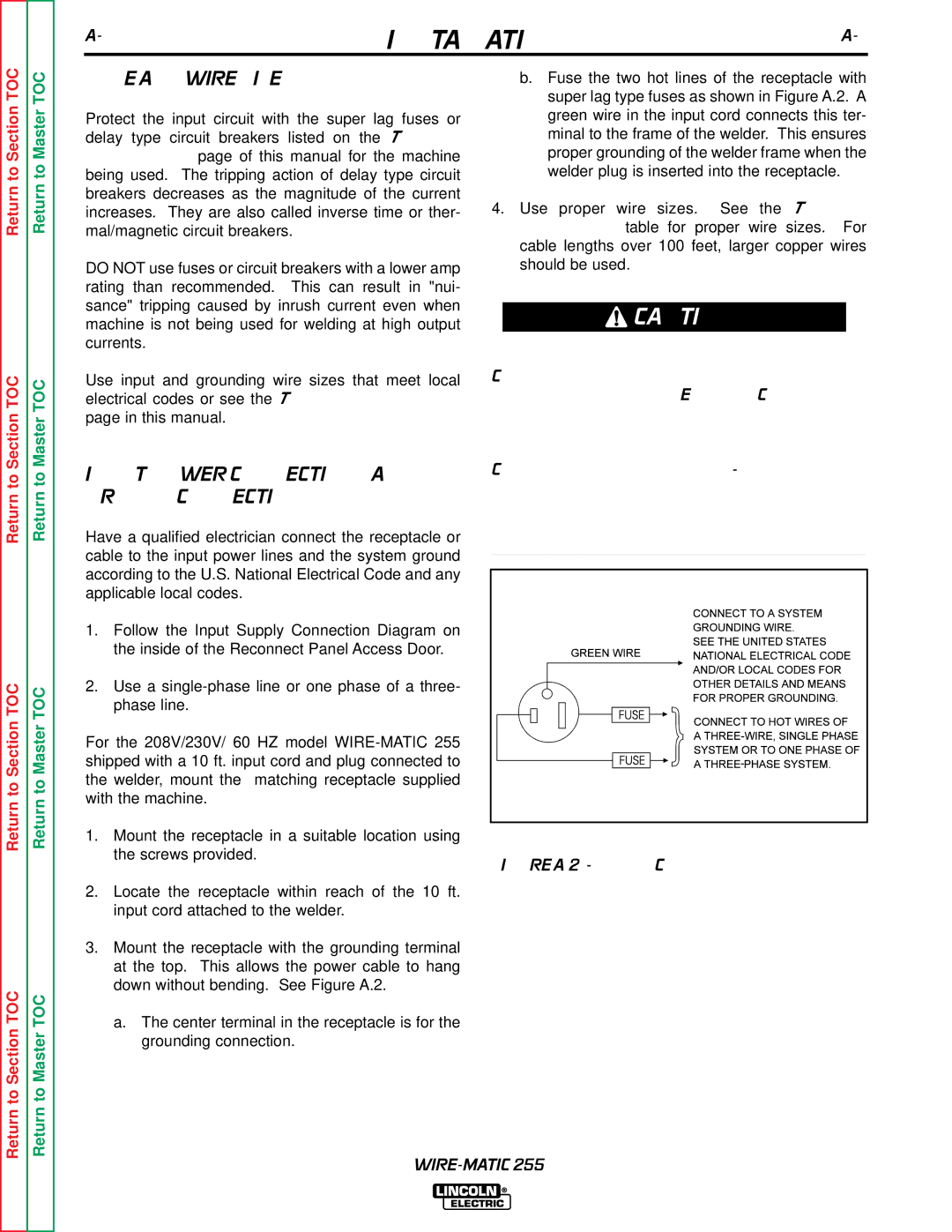
3.Mount the receptacle with the grounding terminal at the top. This allows the power cable to hang down without bending. See Figure A.2.
a.The center terminal in the receptacle is for the grounding connection.
b.Fuse the two hot lines of the receptacle with super lag type fuses as shown in Figure A.2. A green wire in the input cord connects this ter- minal to the frame of the welder. This ensures proper grounding of the welder frame when the welder plug is inserted into the receptacle.
4.Use proper wire sizes. See the Technical Specification table for proper wire sizes. For cable lengths over 100 feet, larger copper wires should be used.
![]() CAUTION
CAUTION
Connect to a system grounding wire. See the United States National Electrical Code and local codes for other details and means for proper grounding.
Connect to hot wires of a
____________________________________ |