TEST PROCEDURE
1.Disconnect main AC input power to the machine.
2.Disconnect Plugs J3 and J6 from the G2803 Control Board. This electrically isolates the SCR bridge assembly. See Figure F.2.
| J3 |
255 CONTROL | G2803 |
WM- | J9 |
|
J6
J4
J5
J1 | J7 | J10 |
|
|
![]()
![]()
![]() J2
J2
FIGURE F.2 - Remove Plugs J3 and J6 to Perform Static SCR Rectifier Assembly Test.
3.Verify that the capacitors have com- pletely discharged with an Analog
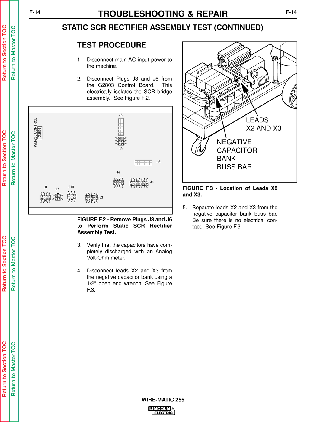
4.Disconnect leads X2 and X3 from the negative capacitor bank using a 1/2" open end wrench. See Figure F.3.
LEADS |
X2 AND X3 |
NEGATIVE |
CAPACITOR |
BANK |
BUSS BAR |
FIGURE F.3 - Location of Leads X2 and X3.
5.Separate leads X2 and X3 from the negative capacitor bank buss bar. Be sure there is no electrical con- tact. See Figure F.3.