|
| INSTALLATION | |||||
|
|
|
| ||||
TOC | TOC | CONNECT OUTPUT COMPONENTS | GUN | LINER AND CONTACT | TIP | ||
|
| INSTALLATION |
| ||||
Section | Master |
|
|
| |||
INSTALL THE WORK CLAMP | The Magnum 250L gun and cable provided with the | ||||||
|
| ||||||
|
|
|
| ||||
to | to | Attach the work clamp to the cable which extends from | |||||
the front of the machine using the following procedure: | |||||||
Return | Return | ||||||
|
| .035” (0.9mm) contact tip. |
| ||||
|
|
|
|
| |||
|
| 1. Insert the lug on the end of the work cable through | 1. If a .045” diameter wire size is to be used, install | ||||
|
|
| the strain relief hole in the work clamp handle. See | ||||
|
|
| Figure A.7. | the .045” contact tip (also provided). |
| ||
|
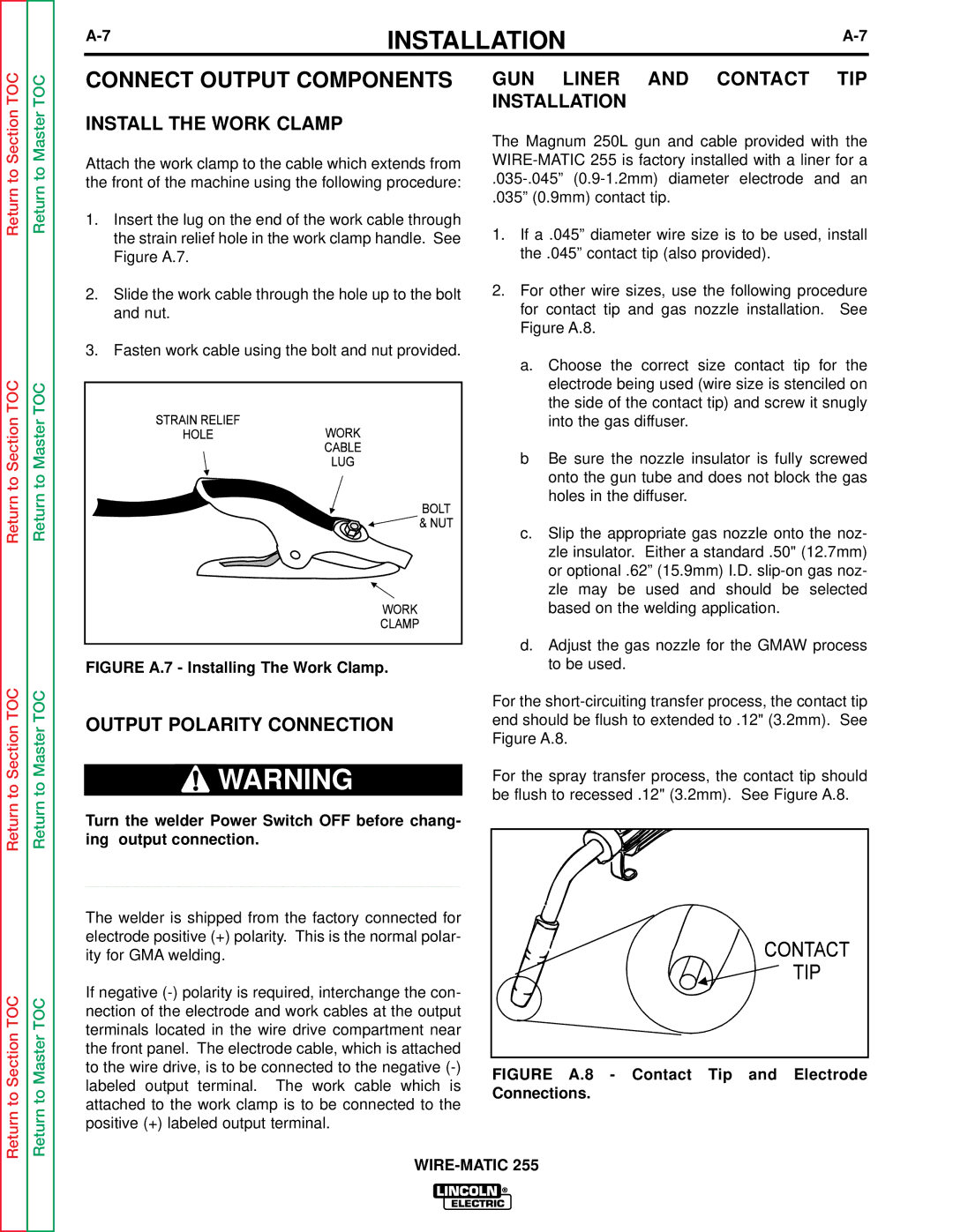
| 2. Slide the work cable through the hole up to the bolt | 2. For other wire sizes, use the following procedure | ||||
|
|
| and nut. | for contact tip and gas nozzle installation. | See | ||
|
|
|
| Figure A.8. |
| ||
3. Fasten work cable using the bolt and nut provided.
|
| a. | Choose the correct size contact tip for the | |
TOC | TOC |
| electrode being used (wire size is stenciled on | |
| the side of the contact tip) and screw it snugly | |||
|
|
| ||
Section | Master |
| into the gas diffuser. | |
b | Be sure the nozzle insulator is fully screwed | |||
|
| |||
to | to |
| onto the gun tube and does not block the gas | |
| holes in the diffuser. | |||
Return | Return |
| ||
c. | Slip the appropriate gas nozzle onto the noz- | |||
|
| |||
|
|
| zle insulator. Either a standard .50" (12.7mm) | |
|
|
| or optional .62” (15.9mm) I.D. | |
|
|
| zle may be used and should be selected | |
|
|
| based on the welding application. | |
|
| d. | Adjust the gas nozzle for the GMAW process | |
|
| FIGURE A.7 - Installing The Work Clamp. | to be used. |
TOC | TOC |
| For the |
|
|
| |
Section | Master | OUTPUT POLARITY CONNECTION | end should be flush to extended to .12" (3.2mm). See |
| Figure A.8. | ||
|
|
|
to | to | WARNING |
| For the spray transfer process, the contact tip should |
|
| |||
|
| be flush to recessed .12" (3.2mm). See Figure A.8. | ||
|
| |||
Return | Return |
|
| |
Turn the welder Power Switch OFF before chang- |
|
| ||
|
|
|
| |
|
| ing output connection. |
|
|
|
| ____________________________________ |
|
|
The welder is shipped from the factory connected for electrode positive (+) polarity. This is the normal polar- ity for GMA welding.
TOC | TOC | If negative |
| |
nection of the electrode and work cables at the output |
| |||
|
|
| ||
Section | Master | terminals located in the wire drive compartment near |
| |
the front panel. The electrode cable, which is attached |
| |||
|
|
| ||
|
| to the wire drive, is to be connected to the negative | FIGURE A.8 - Contact Tip and Electrode | |
|
| labeled output terminal. The work cable which is | ||
to | to | Connections. | ||
attached to the work clamp is to be connected to the | ||||
| ||||
Return | Return |
| ||
positive (+) labeled output terminal. |
| |||
|
|
| ||
|
|
| ||