2 | Getting to Know the SGE2010/SGE2010P |
|
Getting to Know the SGE2010/SGE2010P
This chapter describes the ports, LEDs, and other features on the front and back panels of the switch.
The SGE2010 and SGE2010P are
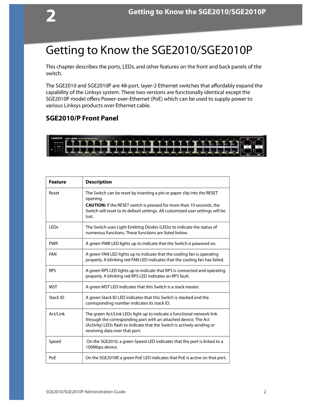
SGE2010/P Front Panel
Feature | Description |
|
|
Reset | The Switch can be reset by inserting a pin or paper clip into the RESET |
| opening. |
| CAUTION: If the RESET switch is pressed for more than 10 seconds, the |
| Switch will reset to its default settings. All customized user settings will be |
| lost. |
|
|
LEDs | The Switch uses Light Emitting Diodes (LEDs) to indicate the status of |
| numerous functions. These functions are listed below. |
|
|
PWR | A green PWR LED lights up to indicate that the Switch is powered on. |
|
|
FAN | A green FAN LED lights up to indicate that the cooling fan is operating |
| properly. A blinking red FAN LED indicates that the cooling fan has failed. |
|
|
RPS | A green RPS LED lights up to indicate that RPS is connected and operating |
| properly. A blinking red RPS LED indicates an RPS fault. |
|
|
MST | A green MST LED indicates that this Switch is a stack master. |
|
|
Stack ID | A green Stack ID LED indicates that this Switch is stacked and the |
| corresponding number indicates its stack ID. |
|
|
Act/Link | The green Act/Link LEDs light up to indicate a functional network link |
| through the corresponding port with an attached device. The Act |
| (Activity) LEDs flash to indicate that the Switch is actively sending or |
| receiving data over that port. |
|
|
Speed | On the SGE2010, a green Speed LED indicates that the port is linked to a |
| 100Mbps device. |
|
|
PoE | On the SGE2010P, a green PoE LED indicates that PoE is active on that port. |
|
|
SGE2010/SGE2010P Administration Guide | 2 |
