Chapter 2
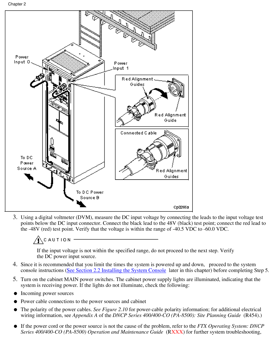
3.Using a digital voltmeter (DVM), measure the DC input voltage by connecting the leads to the input voltage test points below the DC input connector. Connect the black lead to the 48V (black) test point; connect the red lead to the
If the input voltage is not within the specified range, do not proceed to the next step. Verify the DC power input source.
4. Since it is recommended that you limit the times the system is powered up and down, proceed to the system console instructions (See Section 2.2 Installing the System Console later in this chapter) before completing Step 5.
5.Turn on the cabinet MAIN power switches. The cabinet power supply lights are illuminated, indicating that the system is receiving power. If the lights do not illuminate, check the following:
●Incoming power sources
●Power cable connections to the power sources and cabinet
●The polarity of the power cables. See Figure 2.10 for
●If the power cord or the power source is not the cause of the problem, refer to the FTX Operating System: DNCP Series
