Model DH9300 User Guide
Xiva NEW Media Brought to Life
Warranty
Copyright Notice
Retain Your Purchase Receipt
Controls
Remote control action keys
Quick Start Guide
Recording from a CD
Playing Music
Switching on and OFF
Entering Text
For Canadian model
For U.S. model
Information to User
For European model
Important Safety Instructions
Precautions
Equipment Mains Working Setting
HOW to Connect a Plug
General Precautions
Specifications
Introduction
Front View Rear View
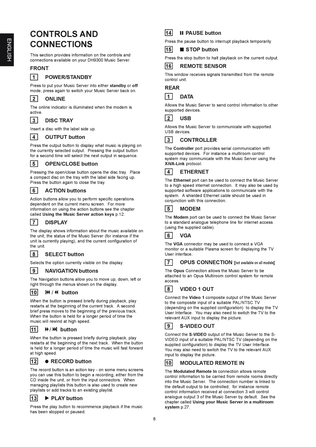
Controls Connections
Digital Optical OUT
Using the Remote Control
Digital Optical
Digital Audio OUT Coaxial
DISC/CH. buttons
Nvolume buttons
Cancel button
Mute button
Configuring Your Remote to Control Other Devices
Connecting Your Music Server
Using the Music Server Action Keys
To enter standby or off mode
To switch on from standby or off mode
TV Screen and Front Panel Display
Music Server Status Icons
Registering Your Music Server
To register your Music Server
To use the alphanumeric keypad
To connect your Music Server to an Internet Account
To select an option from the main menu
Music Server Main Menu
Option Description
Recording Music
To make an auto one-touch recording
Record Quality
Making a custom recording
Tracks
CD information
Listening to music while recording a CD
Playing Music
CD-Text Support
Playing Music from the Library
To browse the library by artist
To browse the library by genre
To select an album, artist, genre or playlist by name
To Browse the library by playlist
Playing Music from a CD
To select a track by number
Controlling Playback
Output Screen
To change the displayed information
Random and repeat playback
To create a new playlist
Using Playlists
Organising Your Music Collection
To select items for a playlist
To edit album information
Editing a Playlist
Entering and Editing Names
Deleting albums, tracks or playlists
Advanced Settings
To display the Settings Menu
System Settings
Output Settings
Basic Configuration
Using Music Server in a Multiroom System
Remote Control USE in a Multiroom System
Output Button
Troubleshooting
Getting Help
Multiroom Control Systems
Cleaning of Exterior Surfaces
Operating Precautions
Repairs
Index
TRACKS, Playing Transport Buttons
English
Carte DE Demarrage Rapide
LES Commandes
Touches d’action de la télécommande
Enregistrement À Partir D’UN CD
Saisie DE Texte
Lecture DE Musique
Activation ET Desactivation
AVANT-PROPOS
Principales Regles D’UTILISATION DE L’APPAREIL
Xiva Naissance D’UN Nouveau Media
Disques Compacts
Bouton DE MARCHE/ARRET
’introduisez aucun disque de forme spéciale
Remarque
VUE Avant
VUE Arriere
Commandes ET Connexions
Digital IN-COAXIALE
Utilisation DE LA Telecommande
Digital OUT-COAXIALE
Analogue Audio OUT
OTouche Mute
NTouches Volume
Touches DISC/CH
Touche Sortie
Mode Arrêt
Mode Veille
Connexion DE Music Server
Affichages DE L’ECRAN DE Television ET DU Panneau Avant
Pour activer le mode Veille ou Arrêt
Pour allumer l’unité à partir du mode Veille ou Arrêt
Utilisation DES Touches D’ACTION DE Music Server
Icônes D’ETAT Music Server
Inscription DE Music Server
Pour inscrire Music Server
Pour utiliser le pavé alphanumérique
Pour connecter Music Server à un compte Internet
Pour sélectionner une option dans le Menu principal
Menu Principal DE Music Server
OptionDescription
Enregistrement Musical
Enregistrement a Partir D’UN CD
Réalisation d’un enregistrement personnalisé
Ecouter de la musique tout en enregistrant un CD
Lecture DE Musique
Prise en charge du CD-Text
Lecture Depuis LA Médiathèque
Pour lire l’intégralité de l’album
Pour parcourir la médiathèque par artiste
Pour parcourir la médiathèque par genre
Pour sélectionner une piste spécifique au sein de l’album
Pour sélectionner une piste par numéro
Pour parcourir la médiathèque par liste de lecture
Lecture Depuis UN CD
Sélection d’un album par numéro
Controle DE LA Lecture
Fenetre DE Sortie
Pour modifier les informations affichées
Lecture aléatoire et lecture en boucle
Pour créer une liste de lecture
Classement DE Votre Collection Musicale
Utilisation DES Listes DE Lecture
Pour sélectionner les éléments de la liste de lecture
Pour modifier le nom d’un élément
Modification d’une liste de lecture
Saisie ET Modification DE Noms
Suppression d’albums, de pistes ou de listes de lecture
Paramètres Avancés
Pour afficher le menu Paramètres
Paramètres du système
Paramètres de sortie
Configuration DE Base
Controle a Distance Dans UN Environnement Multipiece
Systemes DE Controle Multipiece
Assistance
Touche DE Sortie
Depannage
Nettoyage DES Surfaces Externes
Precautions D’EMPLOI
Reparation
Listes DE Lecture
ENREGISTREMENT, Auto
LECTURE, Touche 7
Listes DE Piste
SELECT, Touche 7
System Control Télécommande
VIDEO, Connexion Saisir DE Noms 13
Touches Daction 7
Grabar Desde UN CD
Ficha DE Inicio Rápido
LOS Controles
Botones de acción del mando a distancia
Introducción DE Texto
Reproducción DE Música
Encendido Y Apagado
Prólogo
Precaución
Precauciones
Xiva DA Vida a LOS Nuevos Medios
Botón Power
Discos Compactos
No utilice discos con formas especiales
Especificaciones
Introducción
Nota
Panel Frontal
Panel Posterior
Controles Y Conexiones
Analogue Audio OUT 2, 3
Coaxial Digital OUT
Coaxial Digital
Alimentación
Botones CH./DISC
NBotones de Volumen
10 Botón de Cancelación
OBotón Mute
Modo de espera
Reasignación del control de volumen al usar Music Server
Conexión DE Music Server
Modo apagado
Pantalla DE TV Y Pantalla DEL Panel Frontal
Para activar los modos de espera o apagado
Para activar la unidad desde los modos de espera o apagado
USO DE LOS Botones DE Acción DE Music Server
Iconos DE Estado DE Music Server
Registro DE Music Server
Para registrar Music Server
Usar cuenta de Internet integrada
Para usar los botones alfanuméricos
Para conectar Music Server a una cuenta de Internet
Usar su cuenta de Internet
Para seleccionar una opción del Menú principal
Menú Principal DE Music Server
Opción Descripción
Grabación Desde UN CD
Grabación DE Música
Para realizar una grabación automática un toque
Pistas
Grabación personalizada
Grabación Automática o Personalizada
Calidad de grabación
Audición de música mientras se graba un CD
Reproducción DE Música
Compatibilidad con CD-Text
Reproducción DE Música Desde LA Fonoteca
Para examinar la fonoteca por artistas
Para examinar la fonoteca por géneros
Para seleccionar una pista por número
Para examinar la fonoteca por listas de reproducción
Reproducción DE Música Desde UN CD
Selección de un álbum por número
Control DE Reproducción
Pantalla DE Salida
Para ver otros datos
Reproducción aleatoria y repetida
USO DE Listas DE Reproducción
Organización DEL Material Musical
Para crear una lista de reproducción
Para editar el nombre de un elemento
Edición de una lista de reproducción
Introducción Y Edición DE Nombres
Eliminación de álbumes, pistas o listas de reproducción
Configuración Avanzada
Configuración de sistema
Configuración de salida
USO DEL Mando a Distancia EN UN Sistema Multisala
Configuración Básica
USO DE Music Server EN UN Sistema Multisala
Conector de System Control
EL Botón Output
Resolución DE Problemas
Asistencia
Sistemas DE Control Multisala
Limpieza DE LAS Superficies Exteriores
Precauciones DE USO
Reparaciones
ACCIÓN, Botones DE 7
Índice Alfabético
Malla 13, 23 Mando a Distancia
Panel Frontal
NAVEGACIÓN, Botónes 7 Navegar
OPEN/CLOSE, Botón
VÍDEO, Conexión
VON Einer CD Aufnehmen
Kurzreferenz
DIE Bedienelemente
Aktionstasten auf der Gerätevorderseite
Einbeben VON Texteingeben VON Text
Musik Abspielen
EIN-UND Ausschalten DES Geräts
Vorsichtsmassnahmen
Achtung
Vorwort
Für das europäische Modell
CDs
POWER-TASTE
XiVA- DIE Geburtsstunde Neuer Medien
Technische Daten
Einleitung
Hinweis
Vorderansicht
Rückansicht
Bedienelemente UND Anschlüsse
Digital Audio in Koaxial
Default O/P-TASTE
Digital Audio OUT Koaxial
Netzanschluss
NLAUTSTÄRKE-TASTEN
DISC/CH.-TASTEN
OMUTE-TASTE
ABBRECHEN-TASTE
EIN- UND Ausschalten DES Geräts
Konfigurieren DER Fernbedienung ZUM Steuern Anderer Geräte
ANSCHLIEßEN DES Music Server
Standby-Modus
DIE Anzeige AUF DEM Fernseher UND DER Gerätevorderseite
So aktivieren Sie den Standby- oder Aus- Modus
DIE Music SERVER-AKTIONSTASTEN
Anmelden DES Music Server
Music SERVER-STATUSSYMBOLE
So melden Sie den Music Server an
So verwenden Sie die alphanumerische Tastatur
DAS Music SERVER- Hauptmenü
Option Beschreibung
Aufnehmen VON Einer CD
Aufnehmen VON Musik
So führen Sie eine automatische Aufnahme durch
Aufnahmequalität
Durchführen einer Spezialaufnahme
Titel
CD-Informationen
Wiedergabe von Musik während einer Aufnahme
Wiedergeben VON Musik
Unterstützung von CD-Text
Wiedergeben VON Musik AUS DER Bibliothek
So durchsuchen Sie die Bibliothek nach Künstlern
So durchsuchen Sie die Bibliothek nach Genre
So wählen Sie einen Titel nach Nummer aus
So durchsuchen Sie die Bibliothek nach Playlisten
Wiedergeben Einer CD
Auswählen eines Albums nach Nummer
Wiedergabesteuerung
DER Ausgabebildschirm
So wechseln Sie zwischen den angezeigten Informationen
Zufällige und wiederholte Wiedergabe
So erstellen Sie eine Playliste
Sortieren DER Musiksammlung
Playlisten
So fügen Sie der Playliste Titel hinzu
So bearbeiten Sie den Namen eines Eintrags
Bearbeiten einer Playliste
Eingeben UND Bearbeiten VON Namen
Löschen von Alben, Titeln oder Playlisten
Erweiterte Einstellungen
So zeigen Sie das Menü „Einstellungen an
Systemeinstellungen
Ausgangseinstellungen
Grundkonfiguration
Verwenden DES Music Server in Einem Mehrraumsystem
Fernbedienung in Einem Mehrraumsystem
Mehrraumsteuersysteme
Hilfe
DIE OUTPUT-TASTE
Fehlerbehebung
Reinigen DER AUßENFLÄCHEN
VORSICHTSMAßNAHMEN Beim Betrieb
Reparaturen
ABBRECHEN-TASTE
Bearbeiten Namen
Play Stop
Playlisten Wiedergeben 19 POWER/STANDBY-TASTE 7, 8
Pause
Remote IN-ANSCHLUSS 8, 26 Rückseite
Comandi
Scheda D’AVVIAMENTO Rapido
Registrazione DA UN CD
Inserimento DI Testo
Suonare Musica
Accensione E Spegnimento
Appendix a Annexe a Apéndice a Anhang a
Fujitsu General
Frontech
Fujitsu
Funai
Nikkai
Neckermann
NEI
Nissan
Sharp
Seleco
Sentra
Siarem
AMC
ADC
Adcom
Angstrom
Is a registered trademark