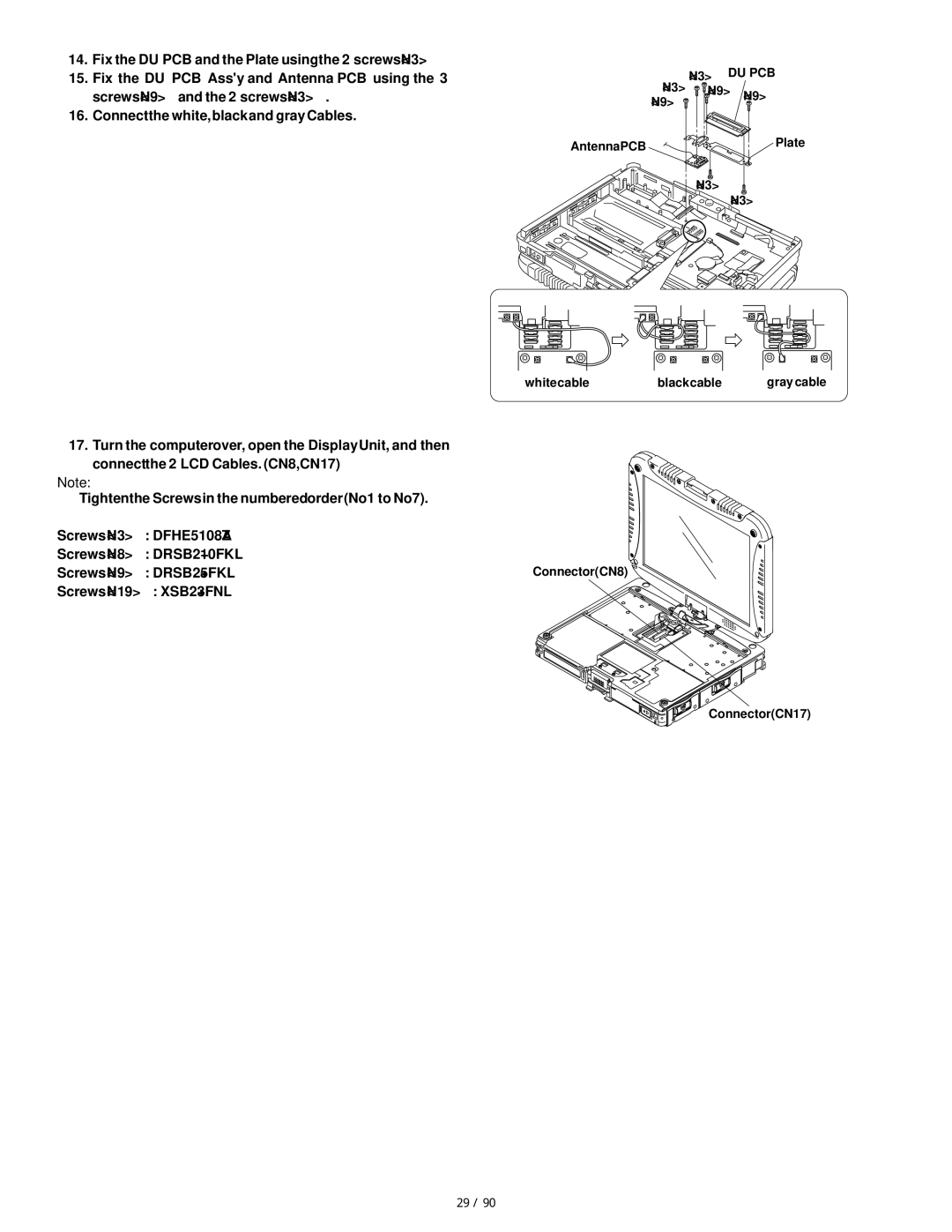
14.Fix the DU PCB and the Plate using the 2 screws <N3>.
15.Fix the DU PCB Ass'y and Antenna PCB using the 3 screws <N9> and the 2 screws <N3> .
16.Connect the white, black and gray Cables.
17.Turn the computer over, open the Display Unit, and then connect the 2 LCD Cables. (CN8,CN17)
Note:
Tighten the Screws in the numbered order (No1 to No7).
Screws <N3> : DFHE5108ZA
Screws <N8> : DRSB2+10FKL
Screws <N9> : DRSB2+5FKL
Screws <N19> : XSB2+3FNL
<N3> DU PCB <N3>  <N9> <N9>
<N9>
Antenna PCB | Plate |
<N3>
<N3>
white cable | black cable | gray cable |
Connector(CN8) ![]()
Connector(CN17) |
50 / 90