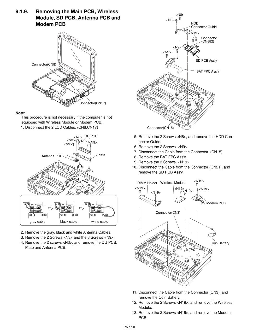
9.1.9.Removing the Main PCB, Wireless Module, SD PCB, Antenna PCB and Modem PCB
<N8>
<N8>
HDD
Connector Guide <N19>
<N19>
Connector (CN882)
<N9> ![]()
<N9>
Connector(CN8) ![]()
SD PCB Ass'y
BAT FPC Ass'y
Connector(CN17) |
Note:
This procedure is not necessary if the computer is not equipped with Wireless Module or Modem PCB.
1. Disconnect the 2 LCD Cables. (CN8,CN17)
<N3> DU PCB <N3> ![]() <N9> <N9>
<N9> <N9>
<N9>
Antenna PCB | Plate |
<N3>
<N3>
gray cable | black cable | white cable |
Connector(CN15)
5.Remove the 2 Screws <N8>, and remove the HDD Con- nector Guide.
6.Remove the 2 Screws. <N9>
7.Disconnect the Cable from the Connector. (CN15)
8.Remove the BAT FPC Ass'y.
9.Remove the 3 Screws. <N19>
10.Disconnect the Cable from the Connector (CN21), and remove the SD PCB Ass'y.
DIMM Holder | Wireless Module | <N19> | |
| |||
<N19> |
| <N19> | <N19> |
<N19> | <N19> |
| |
|
| ||
Modem PCB
Connector(CN3)
2.Remove the gray, black and white Antenna Cables.
3.Remove the 2 Screws <N3> and the 3 Screws <N9>.
4.Remove the 2 screws <N3>, and remove the DU PCB, Plate and Antenna PCB.
Coin Battery
11.Disconnect the Cable from the Connector (CN3), and remove the Coin Battery.
12.Remove the 2 Screws <N19>, and remove the Wireless Module.
13.Remove the 2 Screws <N19>, and remove the Modem PCB.
26 / 90