9.2.7.Setting the Pad PCB and SW PCB
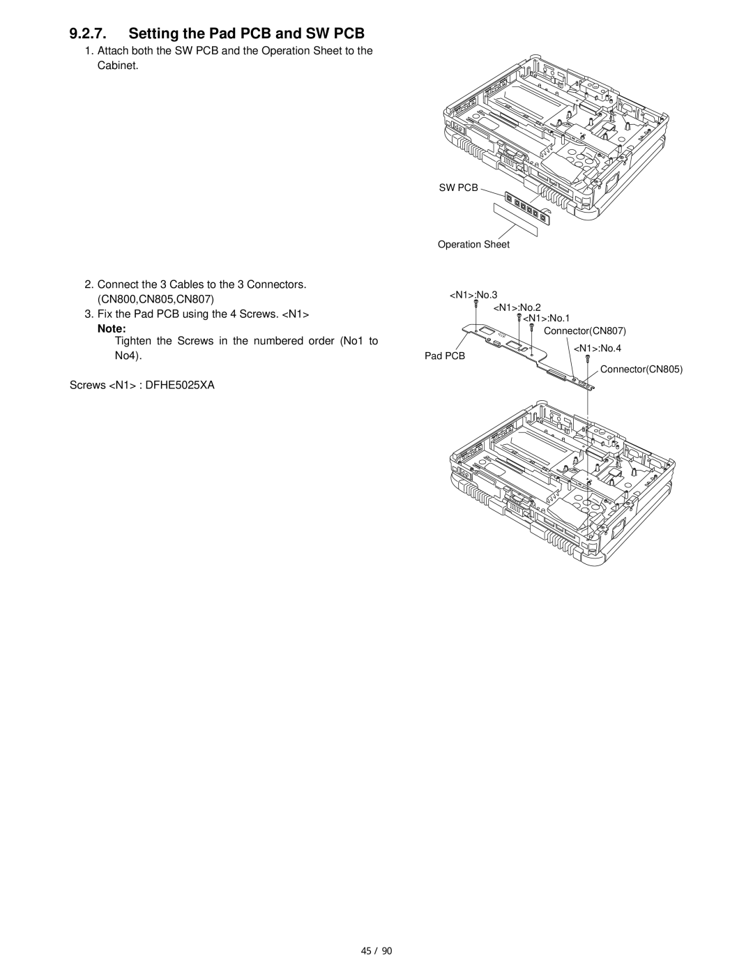
1.Attach both the SW PCB and the Operation Sheet to the Cabinet.
2. | Connect the 3 Cables to the 3 Connectors. |
| (CN800,CN805,CN807) |
3. | Fix the Pad PCB using the 4 Screws. <N1> |
| Note: |
| Tighten the Screws in the numbered order (No1 to |
SW PCB
Operation Sheet
<N1>:No.3
<N1>:No.2
![]() <N1>:No.1
<N1>:No.1 ![]() Connector(CN807)
Connector(CN807)
No4). |
Screws <N1> : DFHE5025XA
Pad PCB
<N1>:No.4
Connector(CN805)
45 / 90