9.1.13. Removing Pad PCB and SW PCB
<N1>
<N1> ![]() <N1>
<N1>
| Connector(CN807) |
Pad PCB | <N1> |
|
Connector(CN805)
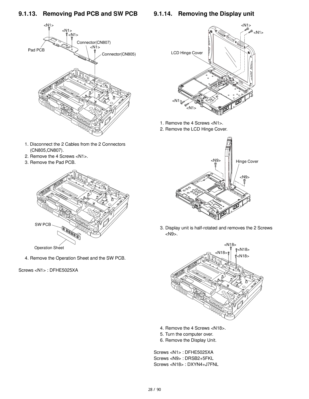
1.Disconnect the 2 Cables from the 2 Connectors (CN805,CN807).
2.Remove the 4 Screws <N1>.
3.Remove the Pad PCB.
SW PCB
9.1.14. Removing the Display unit
<N1>
<N1>
LCD Hinge Cover
<N1> ![]() <N1>
<N1> ![]()
![]()
![]()
![]()
1.Remove the 4 Screws <N1>.
2.Remove the LCD Hinge Cover.
<N9> | Hinge Cover |
<N9>
3.Display unit is
<N18>
Operation Sheet
<N18>
<N18>
4.Remove the Operation Sheet and the SW PCB. Screws <N1> : DFHE5025XA
![]() <N18>
<N18>
4.Remove the 4 Screws <N18>.
5.Turn the computer over.
6.Remove the Display Unit.
Screws <N1> : DFHE5025XA
Screws <N9> : DRSB2+5FKL
Screws <N18> : DXYN4+J7FNL
28 / 90