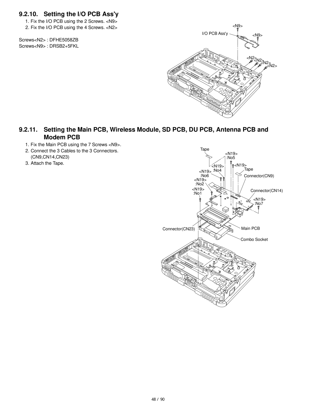
9.2.10. Setting the I/O PCB Ass'y
1. Fix the I/O PCB using the 2 Screws. <N9> |
| <N9> |
2. Fix the I/O PCB using the 4 Screws. <N2> |
| |
| I/O PCB Ass'y | <N9> |
Screws<N2> : DFHE5058ZB |
| |
|
| |
Screws<N9> : DRSB2+5FKL |
|
|
|
| <N2> |
|
| <N2> |
|
| <N2> |
|
| <N2> |
9.2.11.Setting the Main PCB, Wireless Module, SD PCB, DU PCB, Antenna PCB and Modem PCB
1.Fix the Main PCB using the 7 Screws <N9>.
2.Connect the 3 Cables to the 3 Connectors. (CN9,CN14,CN23)
3.Attach the Tape.
Tape
| <N19> | |
| :No5 | |
<N19> | <N19> | |
<N19> :No4 | Tape | |
:No6 | Connector(CN9) | |
<N19> |
| |
:No2 |
| |
<N19> | Connector(CN14) | |
:No1 | ||
| ||
| <N19> | |
| :No7 |
Connector(CN23) | Main PCB |
Combo Socket
48 / 90