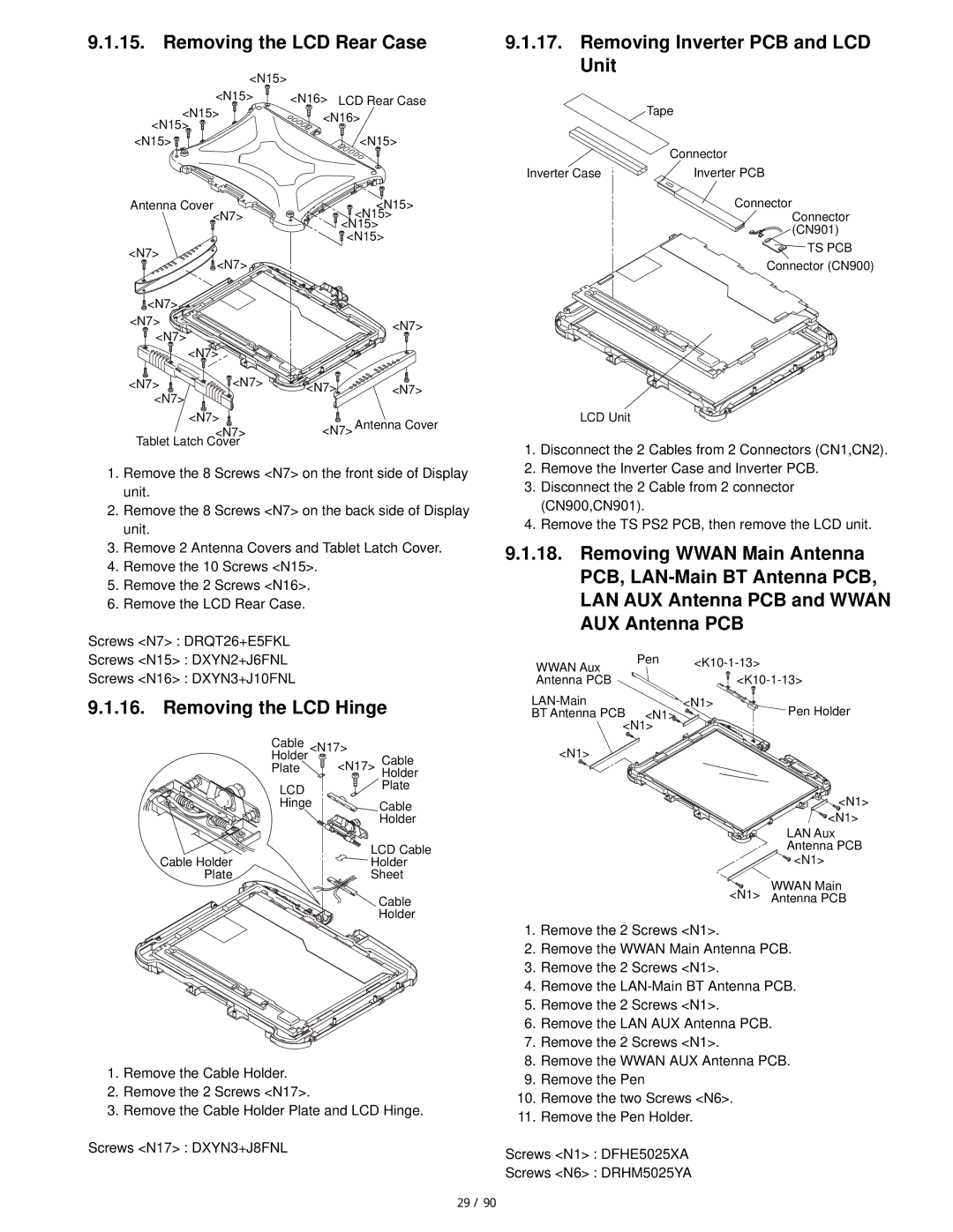
9.1.15. Removing the LCD Rear Case
| <N15> |
|
| |
| <N15> | <N16> | LCD Rear Case | |
<N15> | <N16> | |||
<N15> | ||||
|
| |||
<N15> |
|
| <N15> | |
Antenna Cover |
| <N15> | ||
| <N7> |
| <N15> | |
|
|
| <N15> | |
|
|
| <N15> | |
<N7> | <N7> |
|
| |
|
|
| ||
<N7> |
|
|
| |
<N7> |
|
| <N7> | |
<N7> |
|
| ||
<N7> |
|
| ||
|
|
| ||
<N7> | <N7> | <N7> | <N7> | |
<N7> |
|
|
| |
| <N7> | <N7> Antenna Cover | ||
| <N7> | |||
Tablet Latch Cover |
|
| ||
1.Remove the 8 Screws <N7> on the front side of Display unit.
2.Remove the 8 Screws <N7> on the back side of Display unit.
3.Remove 2 Antenna Covers and Tablet Latch Cover.
4.Remove the 10 Screws <N15>.
5.Remove the 2 Screws <N16>.
6.Remove the LCD Rear Case.
Screws <N7> : DRQT26+E5FKL
Screws <N15> : DXYN2+J6FNL
Screws <N16> : DXYN3+J10FNL
9.1.16. Removing the LCD Hinge
Cable | <N17> |
| |
Holder |
| <N17> | Cable |
Plate |
| ||
| Holder | ||
LCD |
|
| Plate |
Hinge |
| Cable | |
|
|
| Holder |
Cable Holder |
| LCD Cable | |
| Holder | ||
Plate |
| Sheet | |
Cable
Holder
1.Remove the Cable Holder.
2.Remove the 2 Screws <N17>.
3.Remove the Cable Holder Plate and LCD Hinge.
Screws <N17> : DXYN3+J8FNL
9.1.17.Removing Inverter PCB and LCD Unit
| Tape |
| Connector |
Inverter Case | Inverter PCB |
| Connector |
| Connector |
| (CN901) |
| TS PCB |
| Connector (CN900) |
LCD Unit
1.Disconnect the 2 Cables from 2 Connectors (CN1,CN2).
2.Remove the Inverter Case and Inverter PCB.
3.Disconnect the 2 Cable from 2 connector (CN900,CN901).
4.Remove the TS PS2 PCB, then remove the LCD unit.
9.1.18.Removing WWAN Main Antenna PCB,
WWAN Aux | Pen | ||
Antenna PCB |
|
| |
| <N1> | Pen Holder | |
BT Antenna PCB | <N1> | ||
<N1> |
|
| |
<N1> |
|
|
|
![]()
![]() <N1>
<N1>
![]() <N1>
<N1>
LAN Aux Antenna PCB ![]() <N1>
<N1>
WWAN Main
<N1> Antenna PCB
1.Remove the 2 Screws <N1>.
2.Remove the WWAN Main Antenna PCB.
3.Remove the 2 Screws <N1>.
4.Remove the
5.Remove the 2 Screws <N1>.
6.Remove the LAN AUX Antenna PCB.
7.Remove the 2 Screws <N1>.
8.Remove the WWAN AUX Antenna PCB.
9.Remove the Pen
10.Remove the two Screws <N6>.
11.Remove the Pen Holder.
Screws <N1> : DFHE5025XA
Screws <N6> : DRHM5025YA
29 / 90