Mercedes BenzCode Scanner CS1000
Connection Table
Test Lead of Cable | Connection source |
Red | Power |
Black | Ground - To socket 1 |
Yellow | To diagnostic test socket |
Power supply (B+) socket on the vehicle Diagnostic Connectors
Use with the battery extension cable to the vehicle battery | |
Socket 16 (circuit 15 - ignition ON)* | |
| Not present in some models. Use battery +. |
Socket 3 (circuit 30 - Battery+) | |
*Must be performed with the ignition ON to power up the scanner. | |
Ground | |
socket 1 | |
socket 1 | |
socket 1 | |
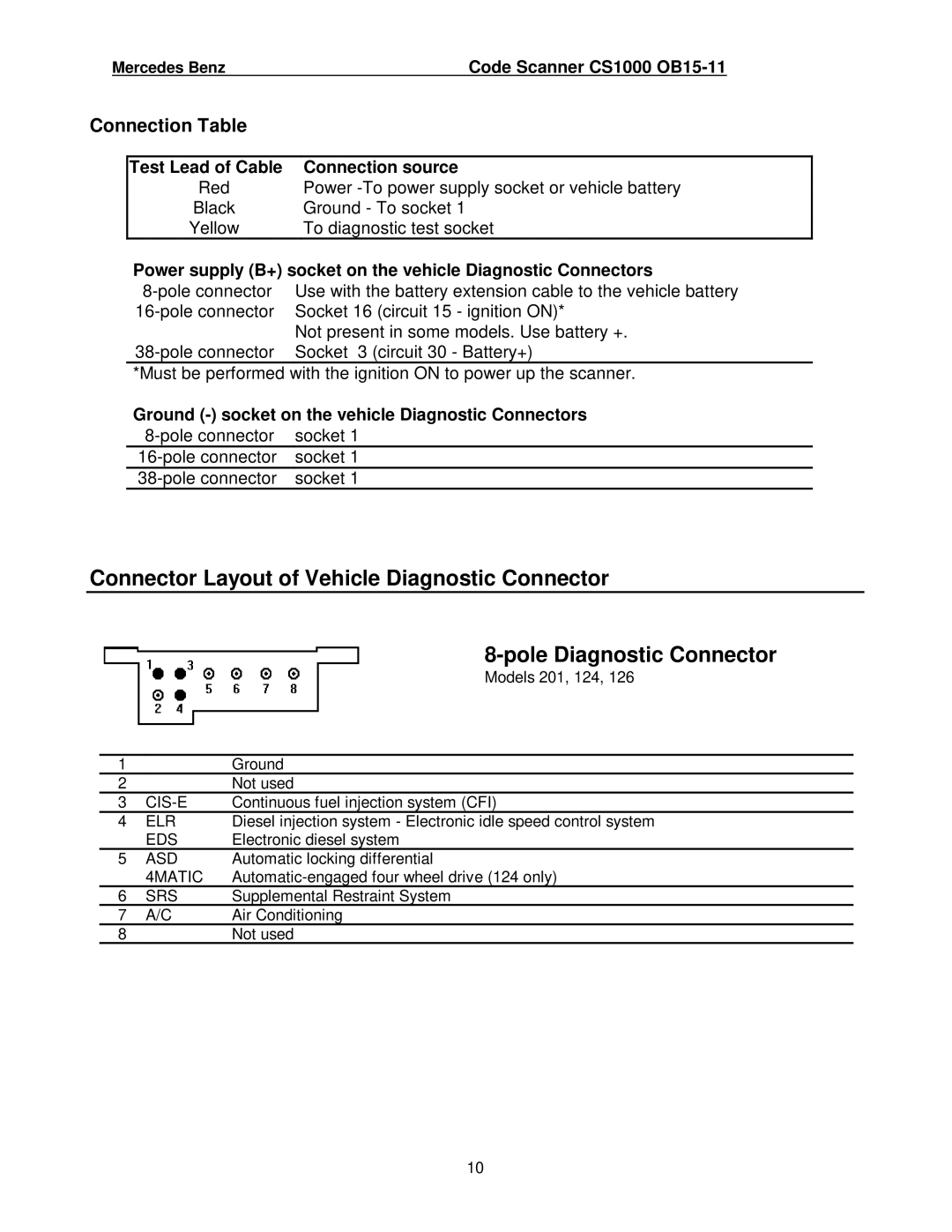
Connector Layout of Vehicle Diagnostic Connector
Models 201, 124, 126
1 |
| Ground |
2 |
| Not used |
3 | Continuous fuel injection system (CFI) | |
4 | ELR | Diesel injection system - Electronic idle speed control system |
| EDS | Electronic diesel system |
5 | ASD | Automatic locking differential |
| 4MATIC | |
6 | SRS | Supplemental Restraint System |
7 | A/C | Air Conditioning |
8 |
| Not used |
10