Chapter 1 Introduction
 NOTE:
NOTE:
Hot-swapping the PSU also removes the cooling module at the lower slot.
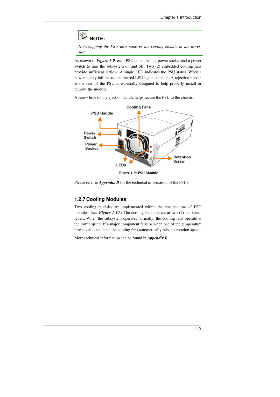
As shown in Figure 1-9, each PSU comes with a power socket and a power switch to turn the subsystem on and off. Two (2) embedded cooling fans provide sufficient airflow. A single LED indicates the PSU status. When a power supply failure occurs, the red LED lights come on. A rejection handle at the rear of the PSU is especially designed to help properly install or remove the module.
A screw hole on the ejection handle helps secure the PSU to the chassis.
Figure 1-9: PSU Module
Please refer to Appendix B for the technical information of the PSUs.
1.2.7 Cooling Modules
Two cooling modules are implemented within the rear sections of PSU modules. (see Figure 1-10.) The cooling fans operate at two (2) fan speed levels. When the subsystem operates normally, the cooling fans operate at the lower speed. If a major component fails or when one of the temperature thresholds is violated, the cooling fans automatically raise its rotation speed.
More technical information can be found in Appendix B.