SecurStor 16i Installation and Hardware Reference Manual
1.2.1 Drive Trays
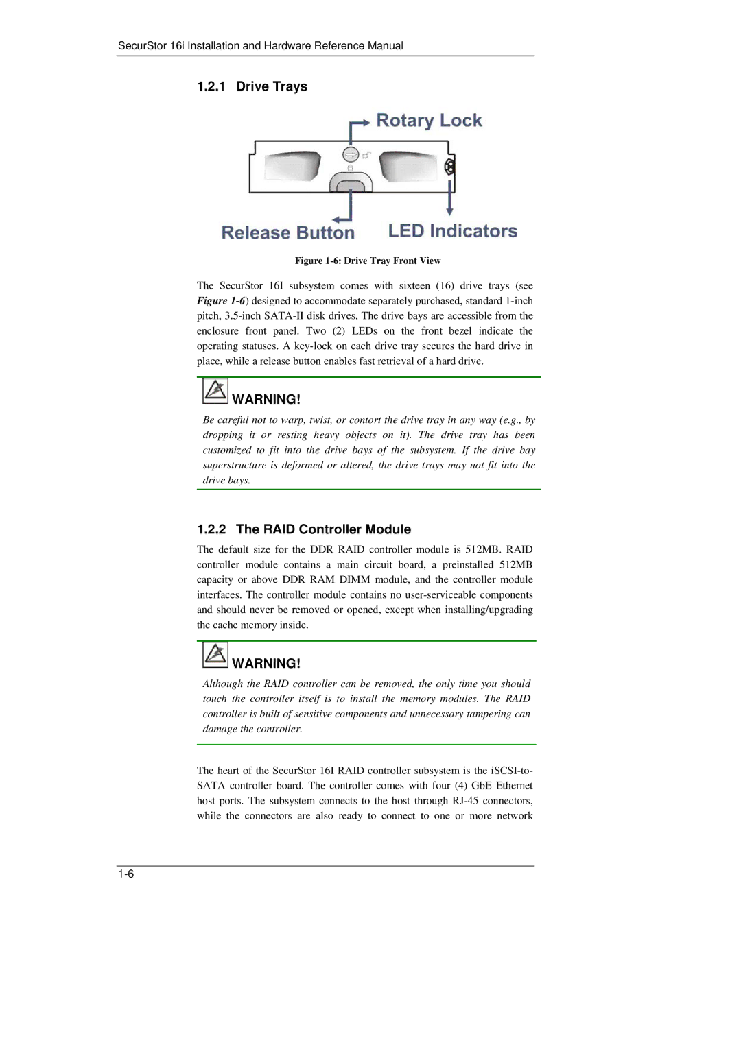
Figure 1-6: Drive Tray Front View
The SecurStor 16I subsystem comes with sixteen (16) drive trays (see Figure
![]() WARNING!
WARNING!
Be careful not to warp, twist, or contort the drive tray in any way (e.g., by dropping it or resting heavy objects on it). The drive tray has been customized to fit into the drive bays of the subsystem. If the drive bay superstructure is deformed or altered, the drive trays may not fit into the drive bays.
1.2.2 The RAID Controller Module
The default size for the DDR RAID controller module is 512MB. RAID controller module contains a main circuit board, a preinstalled 512MB capacity or above DDR RAM DIMM module, and the controller module interfaces. The controller module contains no
![]() WARNING!
WARNING!
Although the RAID controller can be removed, the only time you should touch the controller itself is to install the memory modules. The RAID controller is built of sensitive components and unnecessary tampering can damage the controller.
The heart of the SecurStor 16I RAID controller subsystem is the