Panel Layout and Pin Assignments |
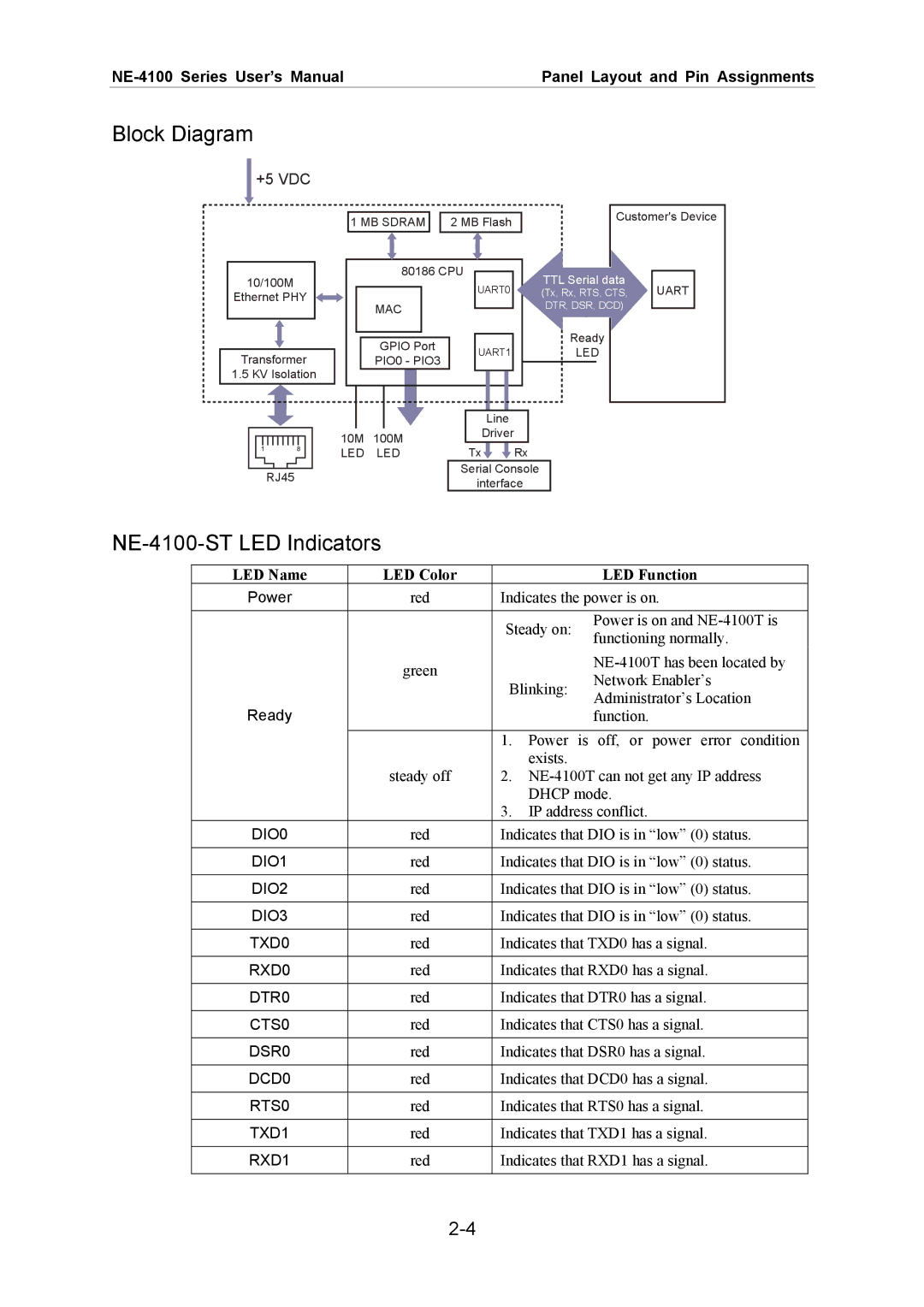
Block Diagram
+5 VDC
10/100M
Ethernet PHY
Transformer
1.5 KV Isolation
1 MB SDRAM ![]()
![]() 2 MB Flash
2 MB Flash
| 80186 CPU |
|
|
| ||
| UART0 | |||||
|
|
|
| |||
| MAC |
|
| |||
|
|
|
|
|
| |
|
|
|
|
|
| |
|
|
|
|
|
|
|
| GPIO Port |
| UART1 | |||
| PIO0 - PIO3 |
| ||||
|
|
|
|
| ||
|
|
|
|
|
|
|
Customer's Device
TTL Serial data |
|
| ||
UART |
| |||
(Tx, Rx, RTS, CTS, |
| |||
DTR, DSR, DCD) |
|
| ||
| Ready |
|
|
|
|
|
|
| |
| LED |
|
|
|
|
|
|
|
|
RJ45
|
|
|
|
|
|
|
|
|
|
|
|
|
|
|
|
|
|
|
| Line |
| ||
10M | 100M |
|
| Driver |
| ||||||
LED | LED |
| Tx |
|
|
| Rx | ||||
|
| ||||||||||
|
|
|
|
| Serial Console | ||||||
|
|
|
|
|
| interface | |||||
NE-4100-ST LED Indicators
LED Name | LED Color |
| LED Function |
Power | red | Indicates the power is on. | |
|
| Steady on: | Power is on and |
|
| functioning normally. | |
|
|
| |
| green |
| |
| Blinking: | Network Enabler’s | |
|
| ||
|
| Administrator’s Location | |
Ready |
|
| |
|
| function. | |
|
| 1. Power is off, or power error condition | |
| steady off | exists. |
|
| 2. | ||
|
| DHCP mode. | |
|
| 3. IP address conflict. | |
DIO0 | red | Indicates that DIO is in “low” (0) status. | |
DIO1 | red | Indicates that DIO is in “low” (0) status. | |
DIO2 | red | Indicates that DIO is in “low” (0) status. | |
DIO3 | red | Indicates that DIO is in “low” (0) status. | |
TXD0 | red | Indicates that TXD0 has a signal. | |
RXD0 | red | Indicates that RXD0 has a signal. | |
DTR0 | red | Indicates that DTR0 has a signal. | |
CTS0 | red | Indicates that CTS0 has a signal. | |
DSR0 | red | Indicates that DSR0 has a signal. | |
DCD0 | red | Indicates that DCD0 has a signal. | |
RTS0 | red | Indicates that RTS0 has a signal. | |
TXD1 | red | Indicates that TXD1 has a signal. | |
RXD1 | red | Indicates that RXD1 has a signal. | |