Getting Started |
Connecting the Power
Connect the 12 VDC power line with the evaluation boards’ power jack. If the power is properly supplied, the “Power” LED will show a solid red color until the system is ready, at which time the “Ready” LED will show a solid green color.
Connecting to the Network
If you are using
LAN |
LAN |
The green indicator LED in the upper right corner blinks when the cable is properly connected to a 100 Mbps Ethernet network, and data is being transmitted.
The yellow indicator LED in the upper left corner blinks when the cable is properly connected to a 10 Mbps Ethernet network, and data is being transmitted.
Connecting to a Serial Device
Connect the serial data cable between the evaluation boards
DI/O Settings
DI/O mode for physical wiring is selected by the DI/O mode jumper. For example, when the DI/O mode of DI/O1 is set to DI, the circuit of DI/O1 on the
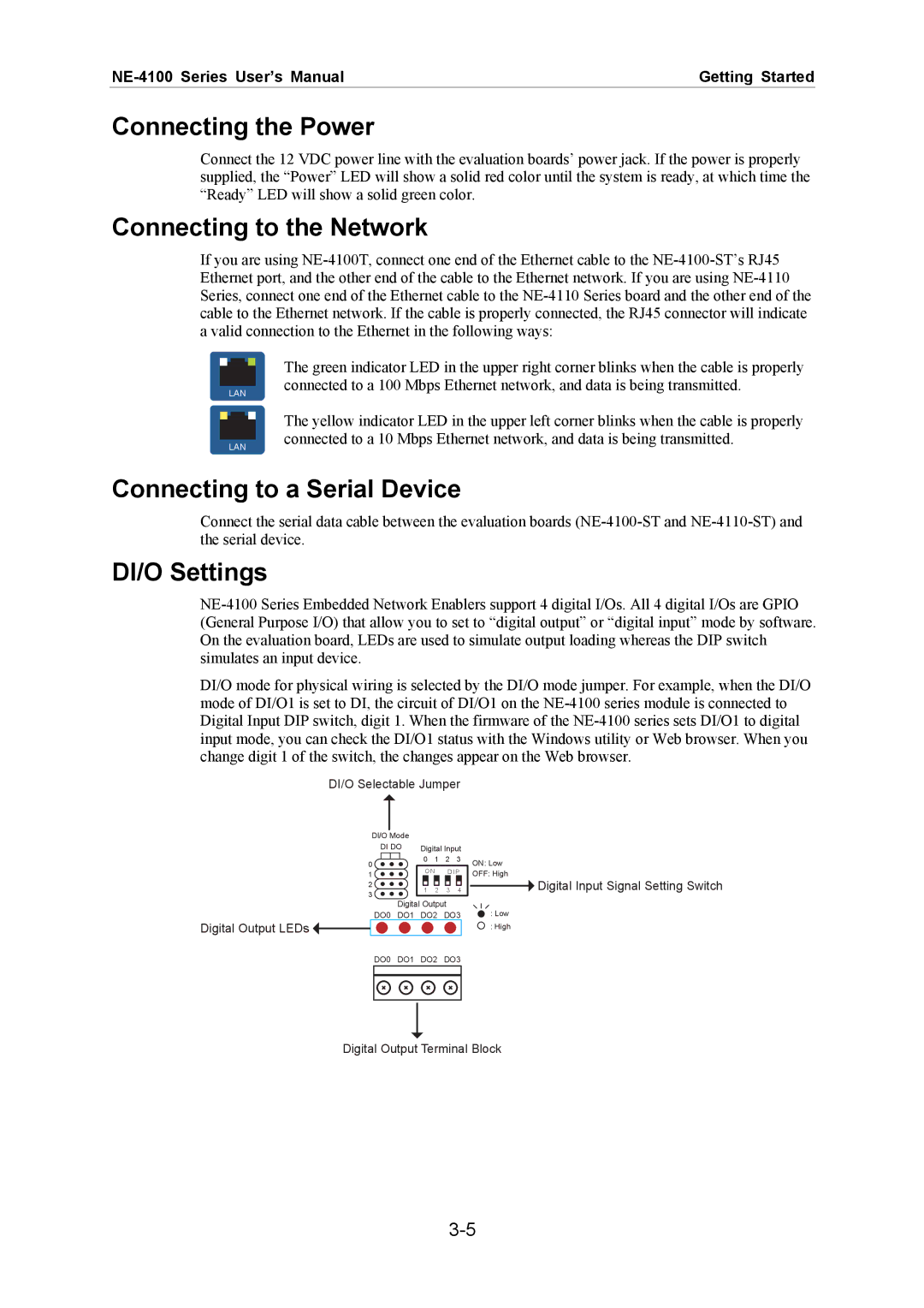
DI/O Selectable Jumper
DI/O Mode |
|
|
|
| |
DI DO | Digital Input | ||||
0 | 0 | 1 | 2 | 3 | |
ON | D I P | ||||
1 | |||||
|
|
|
| ||
2 | 1 | 2 | 3 | 4 | |
3 | |||||
|
|
|
| ||
Digital Output
DO0 DO1 DO2 DO3
Digital Output LEDs ![]()
ON: Low
OFF: High
![]() Digital Input Signal Setting Switch
Digital Input Signal Setting Switch
: Low
: High
DO0 DO1 DO2 DO3
Digital Output Terminal Block