Panel Layout and Pin Assignments |
Pin Assignments
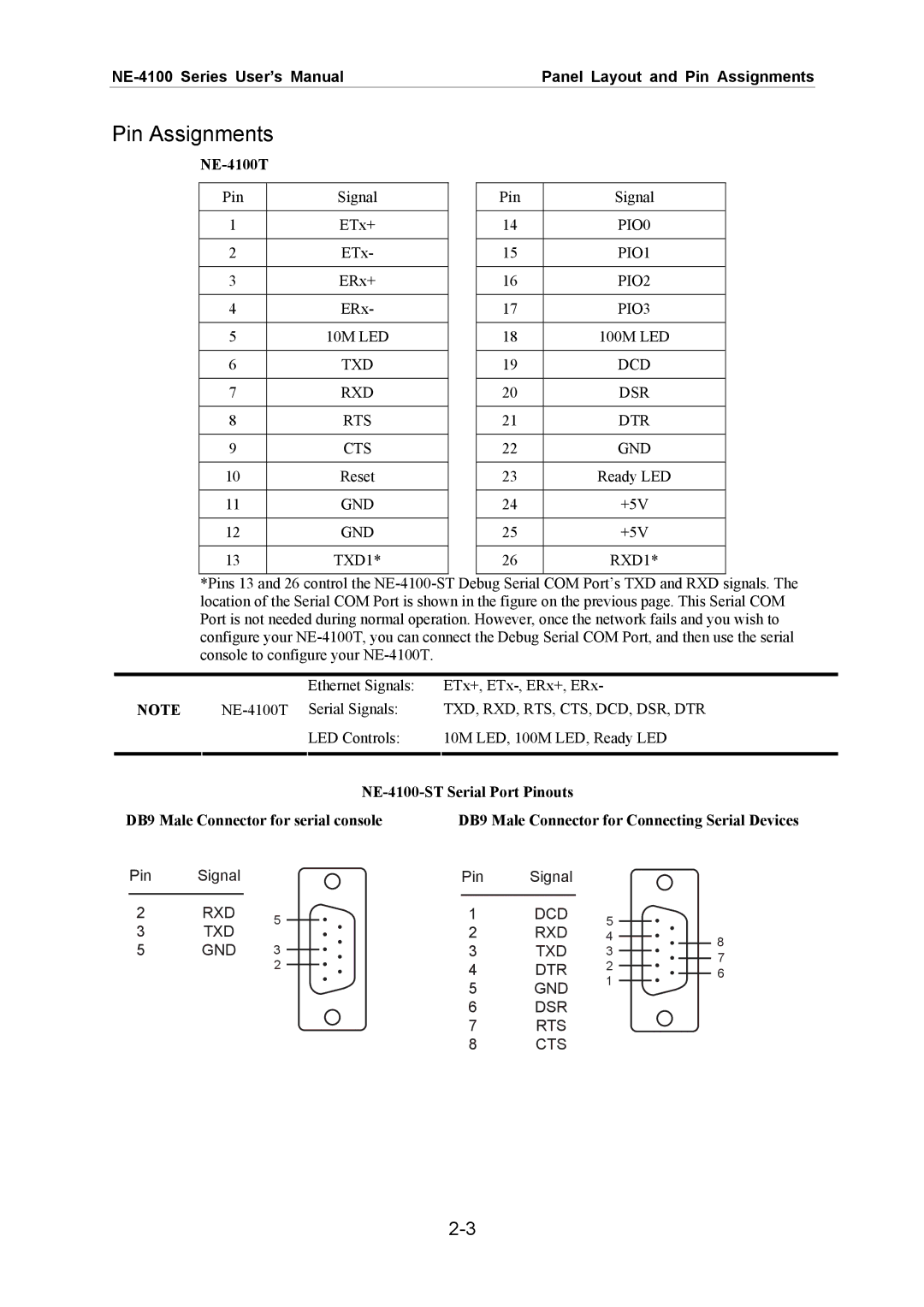
NE-4100T
Pin | Signal |
|
|
1 | ETx+ |
|
|
2 | ETx- |
|
|
3 | ERx+ |
|
|
4 | ERx- |
|
|
5 | 10M LED |
|
|
6 | TXD |
|
|
7 | RXD |
|
|
8 | RTS |
|
|
9 | CTS |
|
|
10 | Reset |
|
|
11 | GND |
|
|
12 | GND |
|
|
13 | TXD1* |
|
|
Pin | Signal |
|
|
14 | PIO0 |
|
|
15 | PIO1 |
|
|
16 | PIO2 |
|
|
17 | PIO3 |
|
|
18 | 100M LED |
|
|
19 | DCD |
|
|
20 | DSR |
|
|
21 | DTR |
|
|
22 | GND |
|
|
23 | Ready LED |
|
|
24 | +5V |
|
|
25 | +5V |
|
|
26 | RXD1* |
|
|
*Pins 13 and 26 control the
|
|
|
|
|
| Ethernet Signals: | ETx+, |
|
|
|
|
| ||||
| NOTE |
| TXD, RXD, RTS, CTS, DCD, DSR, DTR |
| ||||||||||||
|
|
|
|
|
| LED Controls: | 10M LED, 100M LED, Ready LED |
| ||||||||
|
|
|
|
|
|
|
|
|
|
|
|
|
|
|
| |
|
|
|
|
|
|
|
|
|
|
|
| |||||
DB9 Male Connector for serial console | DB9 Male Connector for Connecting Serial Devices | |||||||||||||||
| Pin | Signal |
|
|
|
|
| Pin | Signal |
|
|
|
|
| ||
|
|
|
|
|
|
|
|
|
|
|
|
|
|
|
|
|
2 |
| RXD | 5 |
|
|
| 1 | DCD | 5 |
|
|
|
| |||
3 |
| TXD |
|
|
| 2 | RXD |
|
|
|
| |||||
|
|
|
|
| 4 |
|
|
| 8 | |||||||
|
|
|
|
|
|
|
| |||||||||
5 |
| GND | 3 |
|
|
| 3 | TXD | 3 |
|
|
| ||||
|
|
|
|
|
|
| ||||||||||
|
|
|
|
|
|
| 7 | |||||||||
|
|
|
| 2 |
|
|
| 4 | DTR | 2 |
|
|
| |||
|
|
|
|
|
|
|
|
|
| 6 | ||||||
|
|
|
|
|
|
|
| 1 |
|
|
| |||||
|
|
|
|
|
|
|
| 5 | GND |
|
|
|
| |||
|
|
|
|
|
|
|
|
|
|
|
| |||||
|
|
|
|
|
|
|
|
|
|
|
|
| ||||
|
|
|
|
|
|
|
| 6 | DSR |
|
|
|
|
| ||
|
|
|
|
|
|
|
| 7 | RTS |
|
|
|
|
| ||
|
|
|
|
|
|
|
| 8 | CTS |
|
|
|
|
| ||