PT-7728 User’s Manual Featured Functions
3-31
y Bridge A has been selected as the Root Bridge, since it was determined to have the lowest
Bridge Identifier on the network.
y Since Bridge A is the Root Bridge, it is also the Designated Bridge for LAN segment 1. Port 1
on Bridge A is selected as the Designated Bridge Port for LAN Segment 1.
y Ports 1 of Bridges B, C, X, and Y are all Root Ports sine they are nearest to the Root Bridge,
and therefore have the most efficient path.
y Bridges B and X offer the same Root Path Cost for LAN segment 2. However, Bridge B was
selected as the Designated Bridge for that segment since it has a lower Bridge Identifier. Port
2 on Bridge B is selected as the Designated Bridge Port for LAN Segment 2.
y Bridge C is the Designated Bridge for LAN segment 3, because it has the lowest Root Path
Cost for LAN Segment 3:
y The route through Bridges C and B costs 200 (C to B=100, B to A=100)
y The route through Bridges Y and B costs 300 (Y to B=200, B to A=100)
y The Designated Bridge Port for LAN Segment 3 is Port 2 on Bridge C.
Using STP on a Network with Multiple VLANsIEEE Std 802.1D, 1998 Edition, does not take into account VLANs when calculating STP
information—the calculations only depend on the physical connections. Consequently, some
network configurations will result in VLANs being subdivided into a number of isolated sections
by the STP system. You must ensure that every VLAN configuration on your network takes into
account the expected STP topology and alternative topologies that may result from link failures.
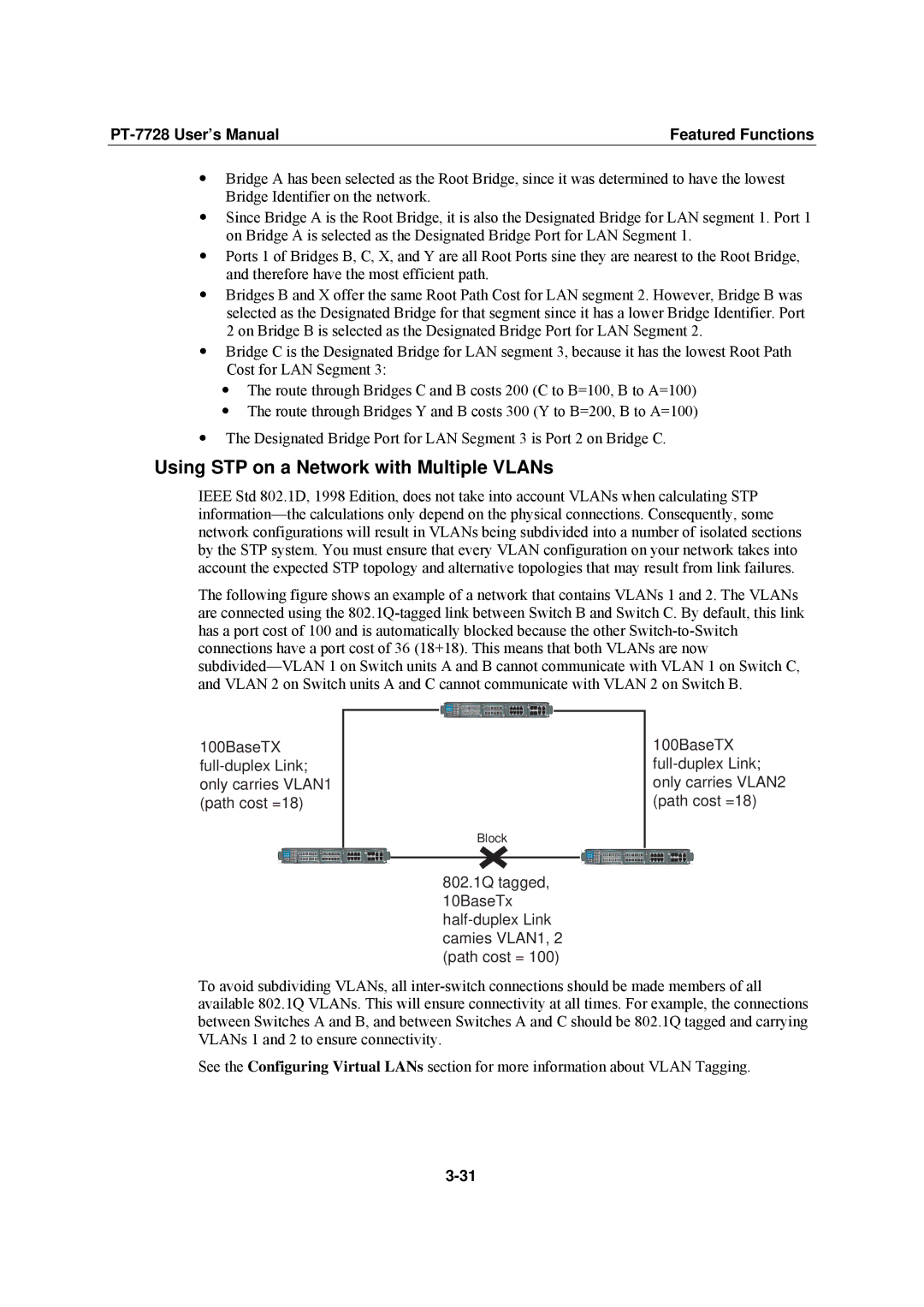
The following figure shows an example of a network that contains VLANs 1 and 2. The VLANs
are connected using the 802.1Q-tagged link between Switch B and Switch C. By default, this link
has a port cost of 100 and is automatically blocked because the other Switch-to-Switch
connections have a port cost of 36 (18+18). This means that both VLANs are now
subdivided—VLAN 1 on Switch units A and B cannot communicate with VLAN 1 on Switch C,
and VLAN 2 on Switch units A and C cannot communicate with VLAN 2 on Switch B.
Block
802.1Q tagged,
10BaseTx
half-duplex Link
camies VLAN1, 2
(path cost = 100)
100BaseTX
full-duplex Link;
only carries VLAN1
(path cost =18)
100BaseTX
full-duplex Link;
only carries VLAN2
(path cost =18)
LNK/ACTSPEEDFDX/HDX
FAULTMASTERCOUPLER
STATPWR1PWR2
RING PORTCOUPLER
PORT
MODE
37
48
26
15
37
48
26
15
4
3
2
1
37
4826
15
M1
M2
M3
M4
LNK/ACTSPEEDFDX/HDX
FAULTMASTERCOUPLER
STATPWR1PWR2
RING PORTCOUPLER
PORT
MODE
37
4826
15
37
4826
15
4
32
1
37
48
26
15
M1
M2
M3
M4
1
2
3
4
5
6
7
8
M3
PT-7728
M4
1
2
3
4
4
1
3
2
135
246
M1
TXRX TX RX TX RX
246
135
M2
TXRX TX RX TX RX
LNK/ACTSPEEDFDX/HDX
FAULTMASTERCOUPLER
STATPWR1PWR2
RING PORTCOUPLER
PORT
MODE
37
48
26
15
37
48
26
15
4
3
2
1
37
4826
15
M1
M2
M3
M4
LNK/ACTSPEEDFDX/HDX
FAULTMASTERCOUPLER
STATPWR1PWR2
RING PORTCOUPLER
PORT
MODE
37
4826
15
37
4826
15
4
32
1
37
48
26
15
M1
M2
M3
M4
1
2
3
4
5
6
7
8
M3
PT-7728
M4
1
2
3
4
4
1
3
2
135
246
M1
TXRX TX RX TX RX
246
135
M2
TXRX TX RX TX RX