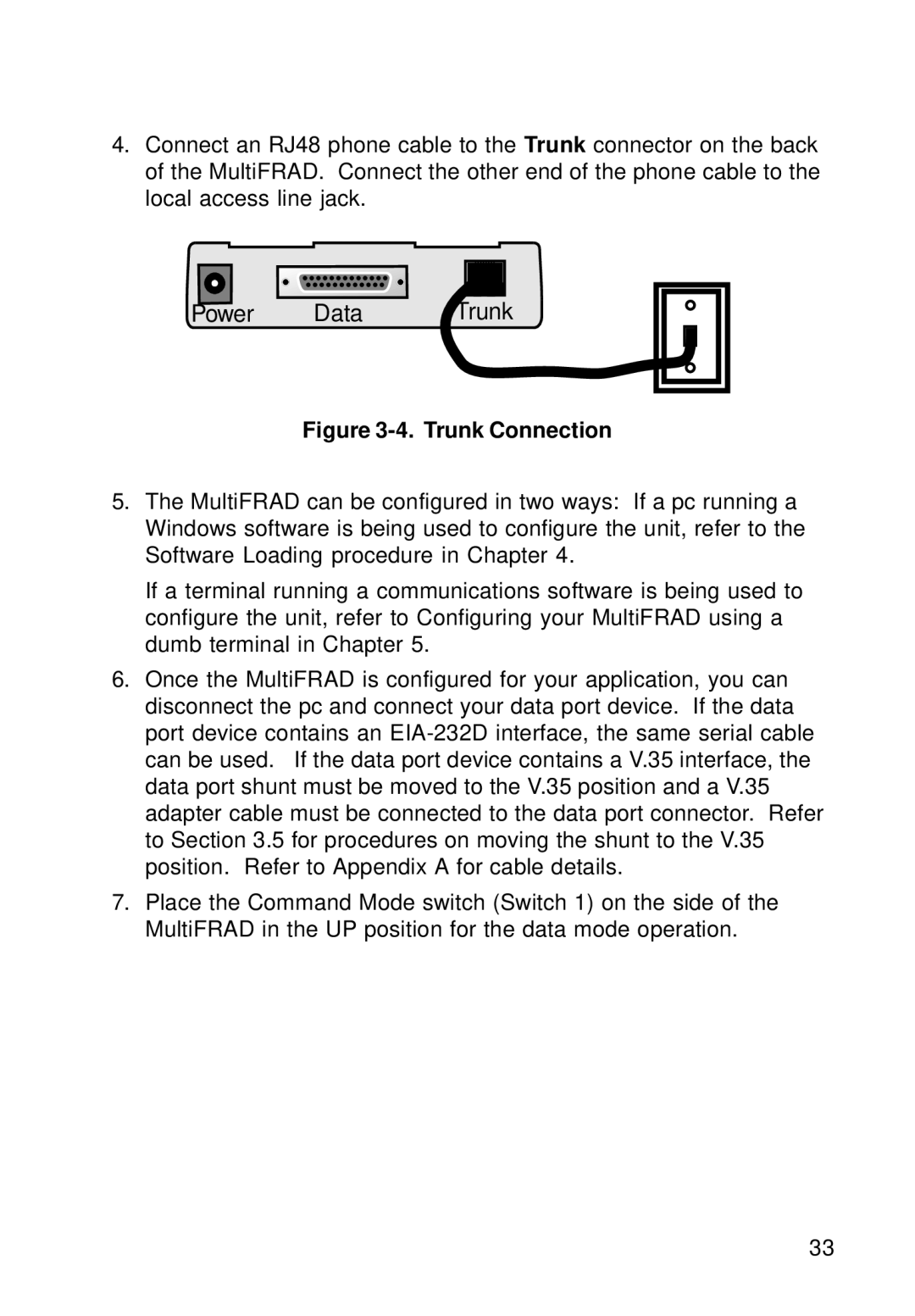
4.Connect an RJ48 phone cable to the Trunk connector on the back of the MultiFRAD. Connect the other end of the phone cable to the local access line jack.
Power | Data | Trunk |
Figure 3-4. Trunk Connection
5.The MultiFRAD can be configured in two ways: If a pc running a Windows software is being used to configure the unit, refer to the Software Loading procedure in Chapter 4.
If a terminal running a communications software is being used to configure the unit, refer to Configuring your MultiFRAD using a dumb terminal in Chapter 5.
6.Once the MultiFRAD is configured for your application, you can disconnect the pc and connect your data port device. If the data port device contains an
7.Place the Command Mode switch (Switch 1) on the side of the MultiFRAD in the UP position for the data mode operation.
33
