Multi-Tech Systems FR111 owner manual Back Panel, Power Connector, Trunk Connector, Data Connector

Models: FR111

1 99
Download 99 pages 3.89 Kb
Page 25
Image 25
2.3Back Panel

2.3Back Panel

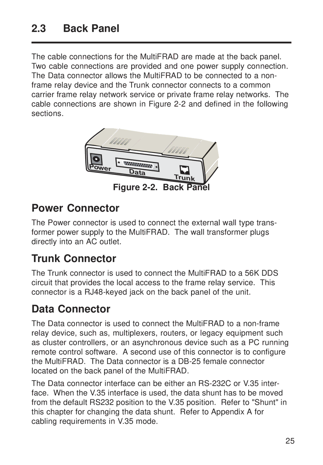
The cable connections for the MultiFRAD are made at the back panel. Two cable connections are provided and one power supply connection. The Data connector allows the MultiFRAD to be connected to a non- frame relay device and the Trunk connector connects to a common carrier frame relay network service or private frame relay networks. The cable connections are shown in Figure 2-2 and defined in the following sections.

Figure 2-2. Back Panel

Power Connector

The Power connector is used to connect the external wall type trans- former power supply to the MultiFRAD. The wall transformer plugs directly into an AC outlet.

Trunk Connector

The Trunk connector is used to connect the MultiFRAD to a 56K DDS circuit that provides the local access to the frame relay service. This connector is a RJ48-keyed jack on the back panel of the unit.

Data Connector

The Data connector is used to connect the MultiFRAD to a non-frame relay device, such as, multiplexers, routers, or legacy equipment such as cluster controllers, or an asynchronous device such as a PC running remote control software. A second use of this connector is to configure the MultiFRAD. The Data connector is a DB-25 female connector located on the back panel of the MultiFRAD.

The Data connector interface can be either an RS-232C or V.35 inter- face. When the V.35 interface is used, the data shunt has to be moved from the default RS232 position to the V.35 position. Refer to "Shunt" in this chapter for changing the data shunt. Refer to Appendix A for cabling requirements in V.35 mode.

25

Page 25
Image 25
Multi-Tech Systems FR111 owner manual Power Connector, Trunk Connector, Data Connector, 2. Back Panel