2.1Introduction
This chapter describes the front panel LEDs and back panel connectors. The front panel has one row of LEDs for both the data channel and trunk status. Two back panel connectors provide the data and trunk connections. A circular power connector is provided to connect the external power supply.
2.2Front Panel
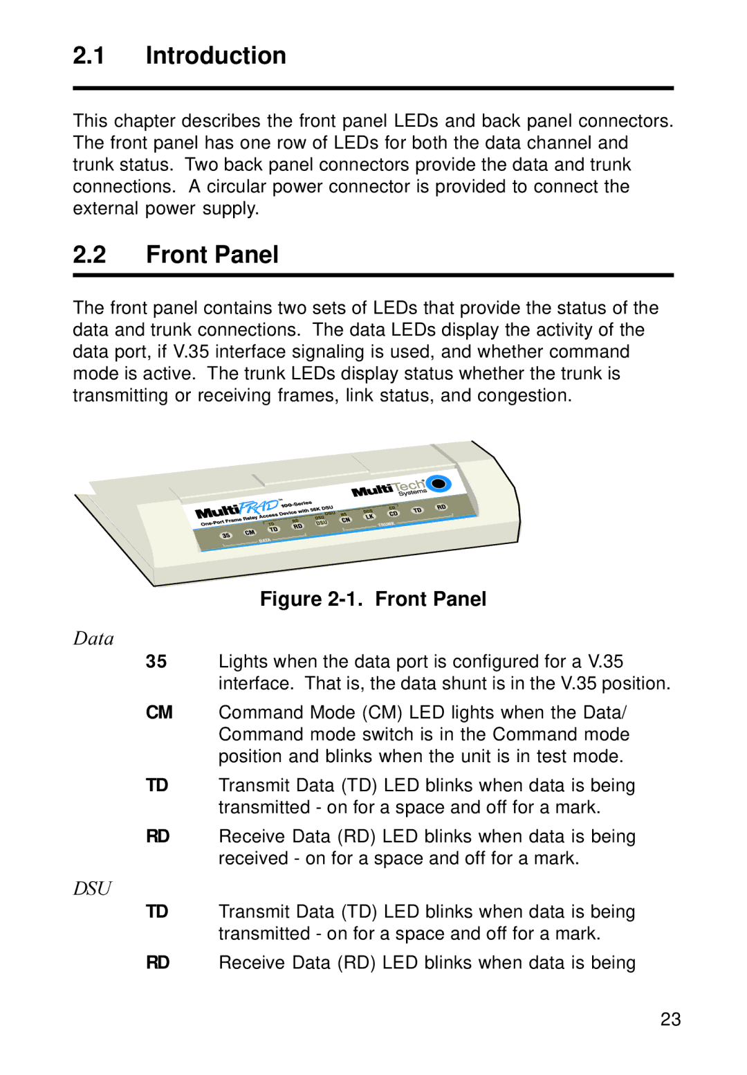
The front panel contains two sets of LEDs that provide the status of the data and trunk connections. The data LEDs display the activity of the data port, if V.35 interface signaling is used, and whether command mode is active. The trunk LEDs display status whether the trunk is transmitting or receiving frames, link status, and congestion.
Figure 2-1. Front Panel
Data
35Lights when the data port is configured for a V.35 interface. That is, the data shunt is in the V.35 position.
CM Command Mode (CM) LED lights when the Data/ Command mode switch is in the Command mode position and blinks when the unit is in test mode.
TD Transmit Data (TD) LED blinks when data is being transmitted - on for a space and off for a mark.
RD Receive Data (RD) LED blinks when data is being received - on for a space and off for a mark.
DSU
TD Transmit Data (TD) LED blinks when data is being transmitted - on for a space and off for a mark.
RD Receive Data (RD) LED blinks when data is being
23