3.4Setup
Use the following steps to setup your MultiFRAD. If V.35 electrical interface signaling is required on the data port, but a pc with
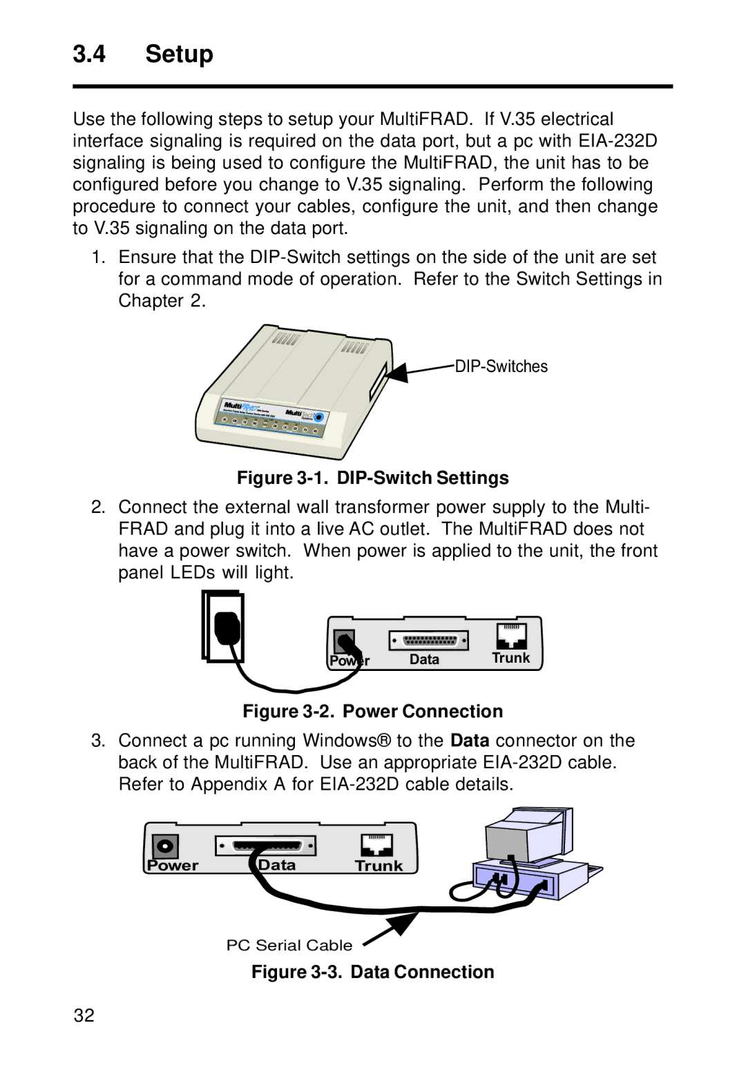
1.Ensure that the
![]()
![]() DIP-Switches
DIP-Switches
Figure 3-1. DIP-Switch Settings
2.Connect the external wall transformer power supply to the Multi- FRAD and plug it into a live AC outlet. The MultiFRAD does not have a power switch. When power is applied to the unit, the front panel LEDs will light.
Power Data Trunk
Figure 3-2. Power Connection
3.Connect a pc running Windows® to theData connector on the back of the MultiFRAD. Use an appropriate
Power Data Trunk
PC Serial Cable
Figure 3-3. Data Connection
32