Chapter 2 - Installation
Cabling your MultiFRAD
Cabling your MultiFRAD involves making the proper Power, Command Port, Ethernet, and Channel connections. Figure
Table 2-1. Cabling Procedure
Step Procedure
1Connect one end of a (supplied) DB25
NOTE: Both channels support the RS232/V.35 protocols, and either asynchronous or HDLC synchronous RS232 data equipment such as multiplexers.
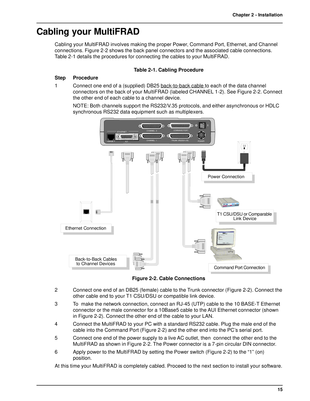
| ETHERNET |
10BASE T | AUI |
CHANNEL 2 | COMMAND PORT |
|
CHANNEL 1 | TRUNK (RS232/V.35) | POWER |
Ethernet Connection
Power Connection
T1 CSU/DSU or Comparable
Link Device
Command Port Connection
Figure 2-2. Cable Connections
2Connect one end of an DB25 (female) cable to the Trunk connector (Figure
3To make the network connection, connect an
4Connect the MultiFRAD to your PC with a standard RS232 cable. Plug the male end of the cable into the Command Port (Figure
5Connect one end of the power supply to a live AC outlet, then connect the other end to the MultiFRAD as shown in Figure
6Apply power to the MultiFRAD by setting the Power switch (Figure
At this time your MultiFRAD is completely cabled. Proceed to the next section to install your software.
15