MultiFRAD II User Guide
Data Port Configuration
This dialog box lets you leave both data ports enabled for normal data transfer operations or disable a given port if you do not want to transmit or receive data over it. The Destination Port parameter will be active only if both data ports have been mapped to the same DLCI.
For
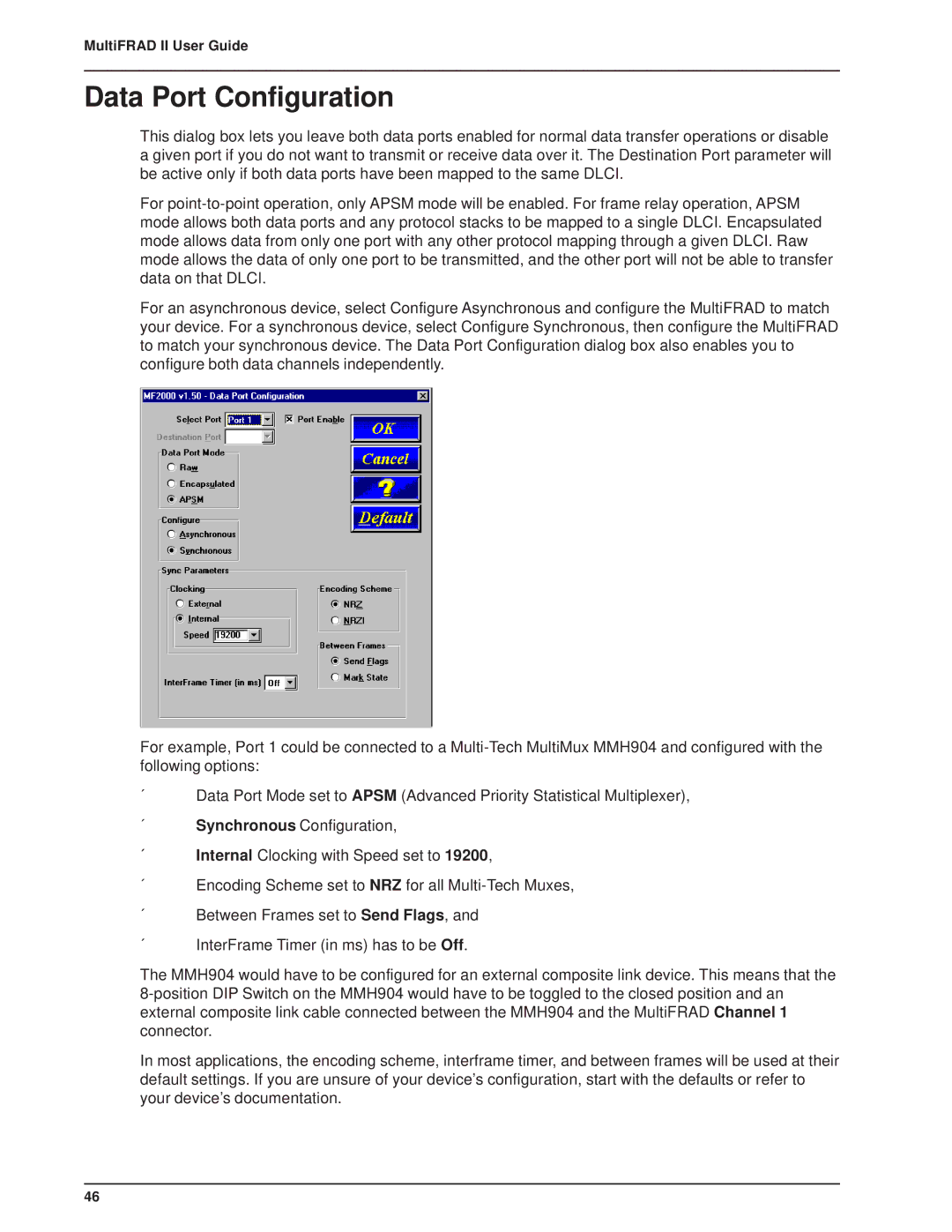
For an asynchronous device, select Configure Asynchronous and configure the MultiFRAD to match your device. For a synchronous device, select Configure Synchronous, then configure the MultiFRAD to match your synchronous device. The Data Port Configuration dialog box also enables you to configure both data channels independently.
For example, Port 1 could be connected to a
´Data Port Mode set to APSM (Advanced Priority Statistical Multiplexer),
´Synchronous Configuration,
´Internal Clocking with Speed set to 19200,
´Encoding Scheme set to NRZ for all
´Between Frames set to Send Flags, and
´InterFrame Timer (in ms) has to be Off.
The MMH904 would have to be configured for an external composite link device. This means that the
In most applications, the encoding scheme, interframe timer, and between frames will be used at their default settings. If you are unsure of your device’s configuration, start with the defaults or refer to your device’s documentation.
46