MultiFRAD II User Guide
Appendix C - Network Overview
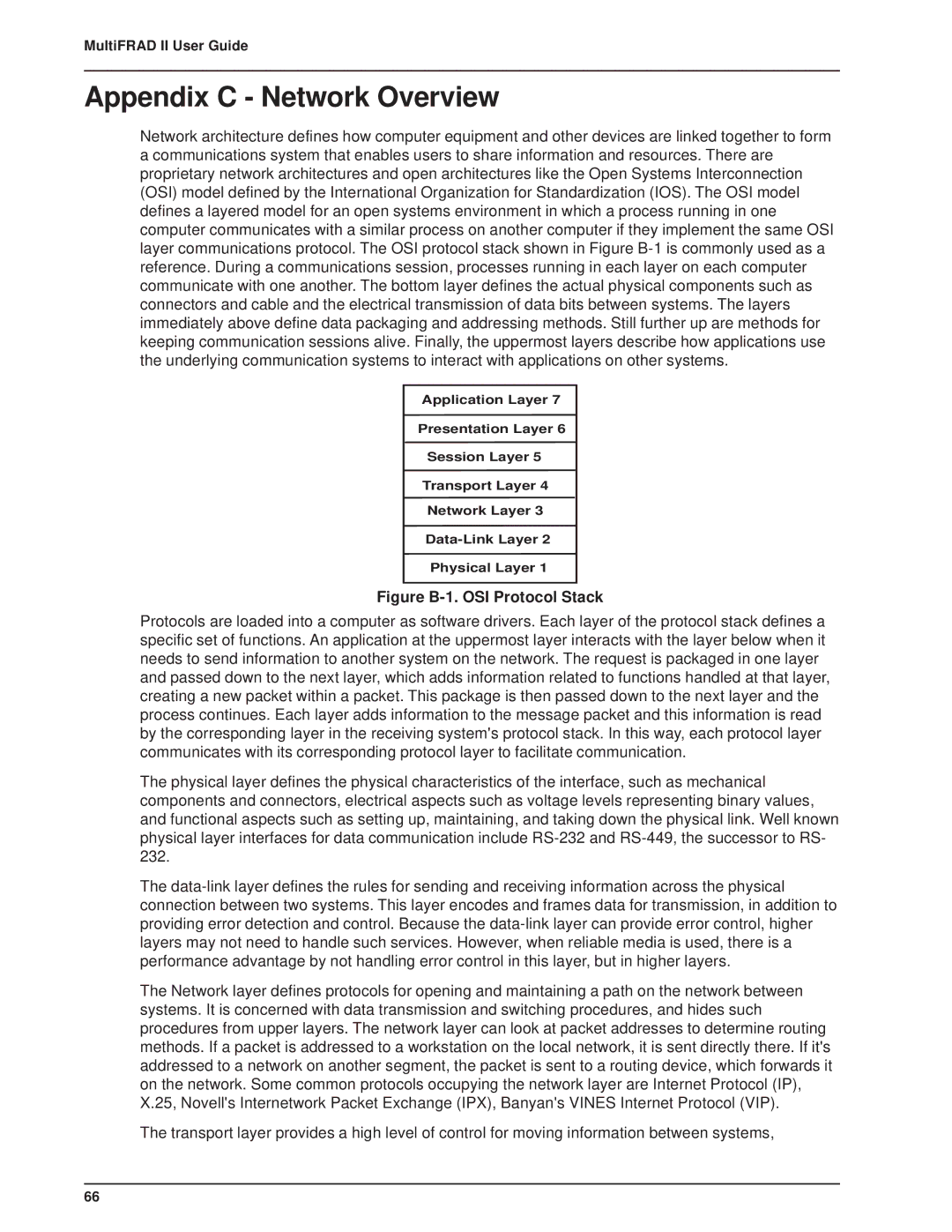
Network architecture defines how computer equipment and other devices are linked together to form a communications system that enables users to share information and resources. There are proprietary network architectures and open architectures like the Open Systems Interconnection (OSI) model defined by the International Organization for Standardization (IOS). The OSI model defines a layered model for an open systems environment in which a process running in one computer communicates with a similar process on another computer if they implement the same OSI layer communications protocol. The OSI protocol stack shown in Figure
Application Layer 7
Presentation Layer 6
Session Layer 5
Transport Layer 4
Network Layer 3
Physical Layer 1
Figure B-1. OSI Protocol Stack
Protocols are loaded into a computer as software drivers. Each layer of the protocol stack defines a specific set of functions. An application at the uppermost layer interacts with the layer below when it needs to send information to another system on the network. The request is packaged in one layer and passed down to the next layer, which adds information related to functions handled at that layer, creating a new packet within a packet. This package is then passed down to the next layer and the process continues. Each layer adds information to the message packet and this information is read by the corresponding layer in the receiving system's protocol stack. In this way, each protocol layer communicates with its corresponding protocol layer to facilitate communication.
The physical layer defines the physical characteristics of the interface, such as mechanical components and connectors, electrical aspects such as voltage levels representing binary values, and functional aspects such as setting up, maintaining, and taking down the physical link. Well known physical layer interfaces for data communication include
The
The Network layer defines protocols for opening and maintaining a path on the network between systems. It is concerned with data transmission and switching procedures, and hides such procedures from upper layers. The network layer can look at packet addresses to determine routing methods. If a packet is addressed to a workstation on the local network, it is sent directly there. If it's addressed to a network on another segment, the packet is sent to a routing device, which forwards it on the network. Some common protocols occupying the network layer are Internet Protocol (IP), X.25, Novell's Internetwork Packet Exchange (IPX), Banyan's VINES Internet Protocol (VIP).
The transport layer provides a high level of control for moving information between systems,
66