MultiFRAD II User Guide
Front Panel Description
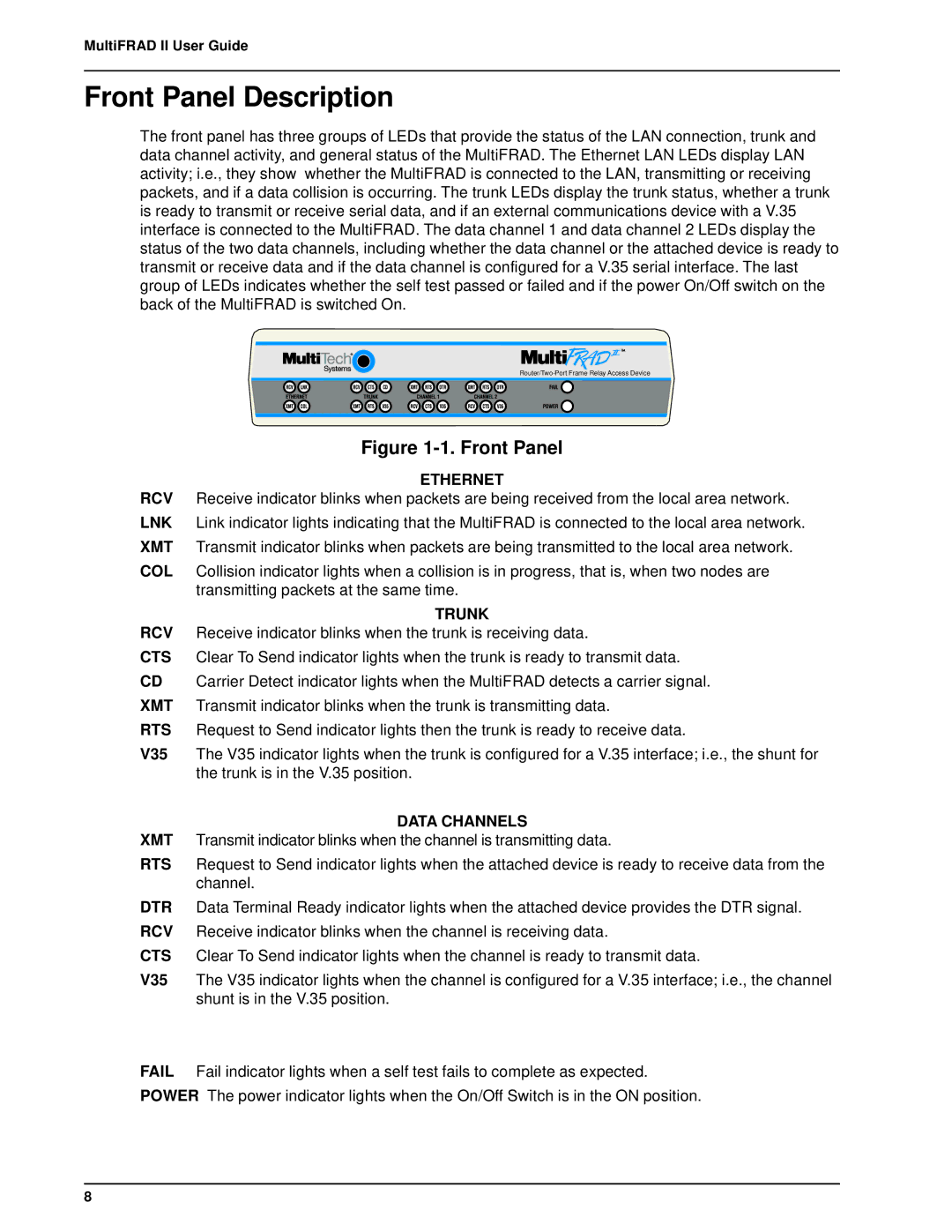
The front panel has three groups of LEDs that provide the status of the LAN connection, trunk and data channel activity, and general status of the MultiFRAD. The Ethernet LAN LEDs display LAN activity; i.e., they show whether the MultiFRAD is connected to the LAN, transmitting or receiving packets, and if a data collision is occurring. The trunk LEDs display the trunk status, whether a trunk is ready to transmit or receive serial data, and if an external communications device with a V.35 interface is connected to the MultiFRAD. The data channel 1 and data channel 2 LEDs display the status of the two data channels, including whether the data channel or the attached device is ready to transmit or receive data and if the data channel is configured for a V.35 serial interface. The last group of LEDs indicates whether the self test passed or failed and if the power On/Off switch on the back of the MultiFRAD is switched On.
Figure 1-1. Front Panel
ETHERNET
RCV Receive indicator blinks when packets are being received from the local area network. LNK Link indicator lights indicating that the MultiFRAD is connected to the local area network. XMT Transmit indicator blinks when packets are being transmitted to the local area network.
COL Collision indicator lights when a collision is in progress, that is, when two nodes are transmitting packets at the same time.
TRUNK
RCV Receive indicator blinks when the trunk is receiving data.
CTS Clear To Send indicator lights when the trunk is ready to transmit data.
CD Carrier Detect indicator lights when the MultiFRAD detects a carrier signal. XMT Transmit indicator blinks when the trunk is transmitting data.
RTS Request to Send indicator lights then the trunk is ready to receive data.
V35 The V35 indicator lights when the trunk is configured for a V.35 interface; i.e., the shunt for the trunk is in the V.35 position.
DATA CHANNELS
XMT Transmit indicator blinks when the channel is transmitting data.
RTS Request to Send indicator lights when the attached device is ready to receive data from the channel.
DTR Data Terminal Ready indicator lights when the attached device provides the DTR signal. RCV Receive indicator blinks when the channel is receiving data.
CTS Clear To Send indicator lights when the channel is ready to transmit data.
V35 The V35 indicator lights when the channel is configured for a V.35 interface; i.e., the channel shunt is in the V.35 position.
FAIL Fail indicator lights when a self test fails to complete as expected.
POWER The power indicator lights when the On/Off Switch is in the ON position.
8