Power supply installation | Standard 1.07 |
PDU terminal blocks and wiring diagram
A PDU consists of eight terminal blocks within a metal enclosure. Before installing the PDU, connect the terminal blocks so that each output connector receives power from a separate
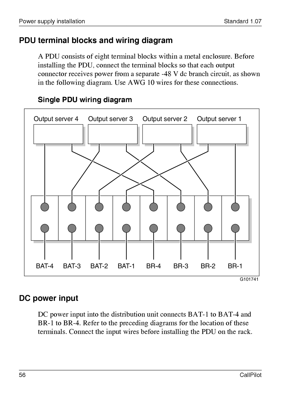
Single PDU wiring diagram
Output server 4 Output server 3 Output server 2 Output server 1
G101741
DC power input
DC power input into the distribution unit connects
56 | CallPilot |