Installing the server and connecting the peripheral devices | Standard 1.07 |
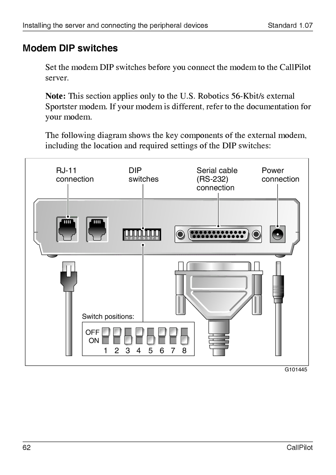
Modem DIP switches
Set the modem DIP switches before you connect the modem to the CallPilot server.
Note: This section applies only to the U.S. Robotics
The following diagram shows the key components of the external modem, including the location and required settings of the DIP switches:
|
| DIP |
|
|
|
|
| Serial cable | Power | |||
connection |
|
| switches |
|
| connection | ||||||
|
|
|
|
|
|
|
|
|
|
| connection |
|
|
| 1 | 2 | 3 | 4 | 5 | 6 | 7 | 8 |
|
|
|
Switch positions: |
|
|
|
|
|
|
|
|
| |||
OFF |
|
|
|
|
|
|
|
|
|
|
|
|
ON |
|
|
|
|
|
|
|
|
|
|
|
|
1 | 2 | 3 |
| 4 |
| 5 | 6 | 7 | 8 |
| ||
|
|
|
|
|
|
|
|
|
|
|
| G101445 |
62 | CallPilot |