TX-NR905
Important Safety Instructions
Avis
Precautions
Power
For models having a power cord with a polarized plug
FCC Information for User
Precautions
For British models
Contents
Features
Supplied Accessories
Make sure you have the following accessories
Power cord
THX Ultra2
Multiroom Capability
Main Room Speakers a and Speakers B
Zone 2 Room Zone 3 Room
Subwoofer Center speaker Surround left and right speakers
Getting to Know the AV Receiver
Front Panel
Getting to Know the AV Receiver
Display
Rear Panel
Sirius antenna on North American model
XM antenna on North American model
AM Antenna not North American model
FM Antenna not North American model
PRE OUT Zone 2, Zone
Zone 2 L/R Speakers
AC Outlet North American and European models only
Remote Controller
Installing the Batteries
Using the Remote Controller
Remote Controller
About the Remote Controller Modes
RECEIVER/TAPE Mode
Listening Mode buttons
Remote Mode buttons
Tape mode
Standby button
DVD Mode
CD/MD/CDR Modes
Dock Mode
Arrow / and Enter buttons
Album +/- button
Previous button
NET/USB Mode
NET/USB Remote Mode button
Next button
Connecting Your Speakers
Enjoying Home Theater
Front left and right speakers
Subwoofer
Connecting Your Speakers
Connecting Your Speakers
About Speakers a and Speakers B
Speakers a
Using Dipole Speakers
Connecting a Powered Subwoofer
Speaker Configuration
Speaker Connection Precautions
Connecting the Speaker Cables
Attaching the Speaker Labels
Strip about 5/8
Channel Playback with Speakers a
Channel Playback with Speakers a or Speakers B
Bi-amping Front Speakers a
Bi-amping Speaker Hookup
Bridging Front Speakers a
Bridged Speaker Hookup
Bi-amping Front Speakers B
Zone 2 R negative terminal to the right
Zone 2 L negative terminal to the left
Bridging Front Speakers B
Connecting Antennas
Connecting the Indoor FM Antenna
Connecting the AM Loop Antenna
Connecting Antennas
Connecting an Outdoor AM Antenna
Connecting an Outdoor FM Antenna
Using a TV/FM Antenna Splitter
Connecting Your Components
About AV Connections
Optical Digital Jacks
AV Connection Color Coding
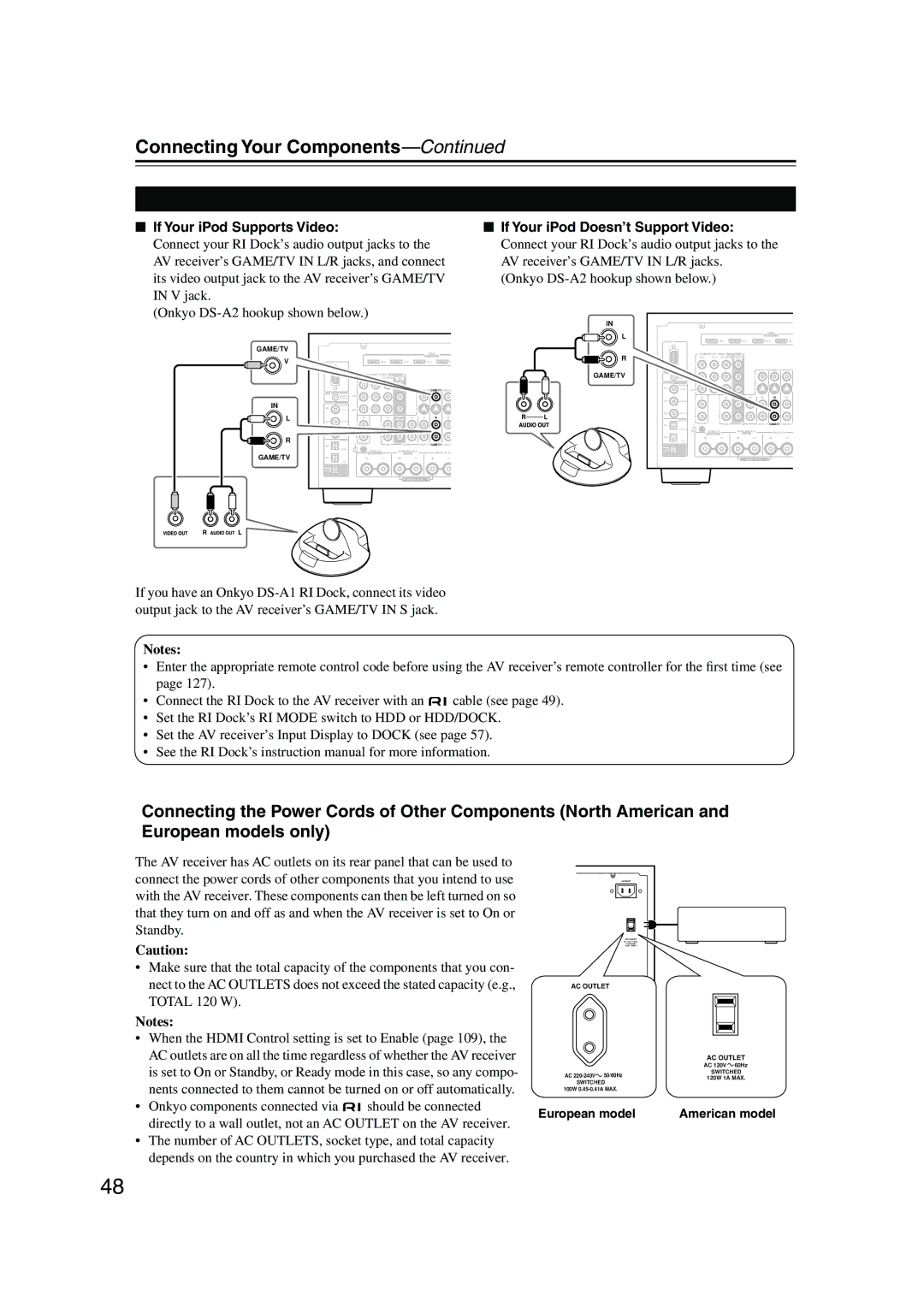
Connecting Your Components
Connecting Audio and Video Signals to the AV Receiver
Hdmi Monitor Setting Set to Main or Sub
Which Connections Should I Use?
Hdmi Monitor Setting Set to No
Audio Connection Formats
Connecting a TV or Projector
Video Connection
Audio Connection
Hint
Connecting a DVD player
Or the other
Hooking Up the Multichannel Input
DVD player
Connecting a VCR or DVR for Playback
VCR or DVR
Connecting a VCR or DVR for Recording
Digital Optical OUT
Satellite, cable, set-top box, etc
Connecting Components with Hdmi
About Hdmi
Supported Audio Formats
About Copyright Protection
Video Signals
Audio Signals
Making Hdmi Connections
Connecting a Game Console
Game Console
Connecting a Camcorder or Other AV Component
Camcorder, etc
Connecting a CD Player
Connecting a Turntable
Step
CD player
Connecting a Cassette, CDR, MiniDisc, or DAT Recorder
Connecting a Power Amplifier
Power amplifier
Connecting an RI Dock
European model
Connecting Onkyo Components
Connecting the Power Cord
Malfunction Some components may not support all Functions
Work
Set the Power switch to the on position
Do the automatic speaker setup-this is essential
Turning On the AV Receiver
Turning On and Standby
First Time Setup
Speaker Settings
First Time Setup
Hdmi Monitor Setup
Press the Setup button
Setup closes
Buttons to select Resolution
Buttons to select 1. Input/Output
Assign, and then press Enter
Hdmi Input Setup
Using the Hdmi OUT Button
Current setting is displayed
Press the Hdmi OUT button
Assign, and then press
Input/Output Assign menu
Appears
Buttons to select 2. Hdmi Input, and then press Enter
Component Video Input Setup
Component Video Input menu appears
IN1 Select if the video component is connected to Compo
IN2 Select if the video component is connected to Compo
Changing the Input Display
Digital Input Setup
These are the default assignments
Digital Input menu appears
Input selector Audio input
Analog Input Setup
Using the Digital Input Button
Picture Quality Menu
Automatic Speaker Setup Audyssey MultEQ XT
Using Audyssey MultEQ XT
Measurement Positions
1st measurement position
Place the setup microphone at
Setup MIC and connect it to the Setup MIC
When prompted, place the setup
Turn on the AV receiver
Error Messages
Speaker Detect Error
Writing Error
Changing the Speaker Settings Manually
Using a Powered Subwoofer
Reviewing the Results
You want to review, and then
TV Format Setup Not North American models
Buttons to select 6. Miscella
Neous, and then press Enter
Buttons to select TV Format
AM Frequency Step Setup on some models
Hardware Setup menu appears
Buttons to select 7. Hardware
Buttons to select AM Freq
Playing Your AV Components
Basic AV Receiver Operation
Tuning into AM/FM Radio Stations
Listening to the Radio
Listening to AM/FM Stations
Tuning into Stations by Frequency
Listening to the Radio
Displaying AM/FM Radio Information
Followed by the D.TUN button
Using RDS
What is RDS?
RDS Program Types PTY
This allows you to search RDS radio stations by type see
Displaying Radio Text RT
Finding Stations by Type PTY
Listening to Traffic News TP
Presetting AM/FM Stations
Selecting Presets
Deleting Presets
Listening to HD Radio Stations North American model only
About HD Radio Stations
Enter
Audio SEL
Selecting the Audio Format Blend Mode
Selecting Multicast Channels
Displaying HD Radio Information
Adjusting Speaker Levels
Setting the Display Brightness
Common Functions
Muting the AV Receiver
Using the Sleep Timer
Using Headphones
Common Functions
Displaying Source Information
Selecting Audio Inputs Specifying the Digital Signal Format
Using the Listening Modes
Selecting with the Remote Controller
Selecting the Listening Modes
Selecting on the AV Receiver
Using the Listening Modes
Listening Modes Available for Each Source Format
Analog and PCM Sources
DSD, Dolby Digital, and Dolby Digital Plus Sources
Sacd
TrueHD and DTS Sources
DTS-ES
DTS-HD Sources
Use this mode with any stereo movie e.g., TV, DVD, VHS
About the Listening Modes
Sound is output by the front left and right speakers
DTS NEO6
DSD
Onkyo Original DSP Modes
Recording
Recording the Input Source
Recording from Different AV Sources
Onscreen Setup Menus
Menu Map
Main menu Submenu
Pages
Adjusting the Listening Modes
Using the Late Night Function
Using the Re-EQ Function
Adjusting the Listening Modes
Audio Adjust
Tone Control Settings
Direct Setting
Multiplex/Mono Settings
PLIIx/Neo6 Settings
Listening Mode Presets
Dolby Digital Settings
Theater-Dimensional Setting
LFE Level Settings
Audio formats supported by that input selector appear
Advanced Setup
Speaker Setup
Speaker Settings
Advanced Setup
Crossover frequency
Low-Pass Filter for the LFE Channel
Double Bass
Setting Speakers a and Speakers B
Press the Down button to
Display the bottom half
Speaker Config screen
Speaker Distance
Speaker Type Front B is set to Not
Speaker Distance screen appears
Press the Receiver Remote Mode button, and then use
Speaker Level Calibration
100
Equalizer Settings
101
THX Audio Setup
102
Source Setup
Setup menu closes
103
Buttons to select THX Sub
IntelliVolume
104
Name Edit
Sync
105
Satellite Radio
Sirius Parental Lock
Miscellaneous Setup
Volume Setup
Volume Display
Maximum Volume
OSD Setup
107
Hardware Setup
Remote Control
108
Zone 2 and Zone
109
Analog Multich
Lock Setup
See Network Settings on
110
Network
111
About NET/USB
Connecting the AV Receiver
112
Network Requirements
113
Playing Music Files on a Server
Windows Media Player 11 Setup
114
Playing Music Files on a USB Device
115
116
Listening to Internet Radio
Network Settings
117
Use the Up and Down Buttons to select a program,
118
Connecting Zone
Connecting Your Zone 2 Speakers Directly to the AV receiver
Connecting Your Zone 2 Speakers to an Amp in Zone
Zone 2 and Zone
Connecting Your Zone 3 Speakers
120
Zone 2 and Zone
Zone 2 Video Output
Powered Zone 2 Setting
Buttons to select Powered
121
Zone 2, and use the Left
Zone 2/Zone 3 Out Settings
Using Zone 2 and Zone
122
Use the Up and Down Buttons to select 2. Zone
On the remote controller, press
123
Selecting an Input Source for Zones
Turning Off Zones
Adjusting the Volume of Zones Muting Zones
Adjusting the Tone of Zone
Adjusting the Balance of Zones
124
Using a Multiroom Kit with Zone 2/3
Using a Multiroom Kit with a Cabinet
Using a Multiroom Kit with Other Components
125
Entering Remote Control Codes
Controlling Other Components
126
Resetting the Remote Controller
Remote Control Codes for Onkyo Components Connected via
Resetting the Remote Mode Buttons
127
128
Learning Commands
129
Using Macros
130
Making Macros
Running Macros
Troubleshooting
131
Troubleshooting
132
133
134
Specifications
135
Onkyo U.S.A. Corporation
Onkyo Europe Electronics GmbH
Onkyo Europe UK Office
Onkyo China Limited