8310 MVL and 8510 DSL Card Configuration
DSL Configuration Service Node Screens
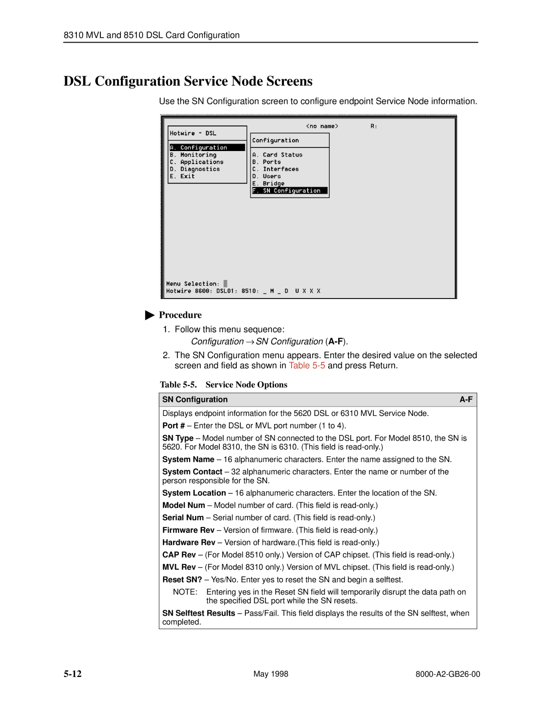
Use the SN Configuration screen to configure endpoint Service Node information.
"Procedure
1.Follow this menu sequence:
Configuration → SN Configuration (A-F).
2.The SN Configuration menu appears. Enter the desired value on the selected screen and field as shown in Table
Table 5-5. Service Node Options
SN Configuration | |
|
|
Displays endpoint information for the 5620 DSL or 6310 MVL Service Node.
Port # ± Enter the DSL or MVL port number (1 to 4).
SN Type ± Model number of SN connected to the DSL port. For Model 8510, the SN is 5620. For Model 8310, the SN is 6310. (This field is
System Name ± 16 alphanumeric characters. Enter the name assigned to the SN.
System Contact ± 32 alphanumeric characters. Enter the name or number of the person responsible for the SN.
System Location ± 16 alphanumeric characters. Enter the location of the SN.
Model Num ± Model number of card. (This field is
Serial Num ± Serial number of card. (This field is
Firmware Rev ± Version of firmware. (This field is
Hardware Rev ± Version of hardware.(This field is
CAP Rev ± (For Model 8510 only.) Version of CAP chipset. (This field is
MVL Rev ± (For Model 8310 only.) Version of MVL chipset. (This field is
Reset SN? ± Yes/No. Enter yes to reset the SN and begin a selftest.
NOTE: Entering yes in the Reset SN field will temporarily disrupt the data path on the specified DSL port while the SN resets.
SN Selftest Results ± Pass/Fail. This field displays the results of the SN selftest, when completed.
May 1998 |